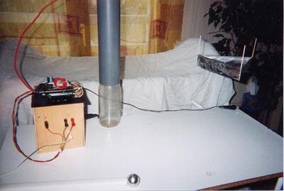
The
Lifters successful replications
Experimenters
Log Book
created
on October 10th, 2001- JLN Labs
All informations in this page are published free and
are intended for private/educational purposes and not for
commercial applications
Lifter replications Log Book : Previous Page - Next Page
|
I just got my first lifter to fly! Hovers at
about 4 CM.
Materials:
Balsa
Aluminum Foil
30awg magnet wire
Super Glue
Brush on (liquid) electric tape
Dimensions:
Sides- 20cm
Foil- 28mm high
Wire gap- 3cm
balsa feet- 25mm
I used the basic lifter design except I used a plastic drinking
straw for the top 20cm supports. The foil then wrapped over it
nice and round. The bottom 20cm supports were balsa.
I also applied something called brush-on electric tape, that I
found it the local Hardware store. I applied this to the balsa
uprights and on the wire and foil at the corners.
I noted it is a good idea to wear rubber gloves when building and
handling lifters as the oil in your fingers is very conductive at
these voltages(fire! fire!). Also use toothpick thin balsa. My
first two attempts were to heavy.
Best Regards
James White
Waterford, MI USA
|
Dear Jean-Louis,
my first lifter is a success! Thanks for your work, you opened the way to a reliable international group cooperation, and I am persuaded it will lead us to new discoveries soon or later.
You can place if you wish some pictures of my Lifter in your "world page", they are online at http://ether.sciences.free.fr/Lifters.htm . Note the thumbs at the top are only there to present the webpage, and the real pictures are just after the updated text.

Best regards, CD
|
|||||||||
| Envoyé via Internet | |||||||||
Hello!
My name is Takashi Maruyama, from Tokyo Japan.
I have successfuly tested the lifter.
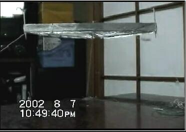
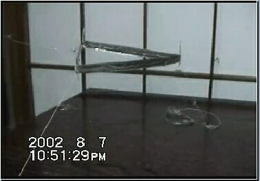
Specs:
Length:200mm
Height of foil:15mm
Foil-Wire-Gap:30mm
Weight:approx 5g
Power Source: 14inch color monitor
Have a good week-end.
Takashi Maruyama
E_mail j02778_maruyama@m1.jrc.co.jp
|
|||||||||
| Envoyé via Internet (afficher l'en-tête) | |||||||||
JLN,
Thanks for your wonderful website! We are busy up here in
Idaho. I posted this to the JLN discussion group a couple of
months ago but it never made it
to the lifter replication page. I built it because I just had
to see for myself.
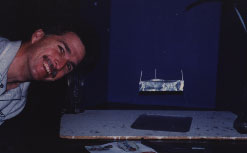
Add Coeur d'Alene Idaho to the list of successful lifter sites:
Lifter 1 clone (thanks JLN!)
Specs:
Thrift store Zenith 19 inch color TV for power supply.
Works with either polarization, however it works better with the
positive electrode connected to the foil and negative connected
to the wire, which seems to be the opposite of other folks
experience. (I wonder Why?)
|
|||||||||||
Hi all,
finally I managed to make my lifter to levitate :-)
One reason probably was that the wires which I used to connect
the anode and kathode were too stiff, but I think the main reason
was that I placed the wood-panel on my table with a plastic table
cloth. So maybe electro-static effect prevented it from lifting
completely.
I replaced the stiffer wire with a very fine one and put it on my
wooden floor and IT LIFTED :-)
Images of the second flight are here:
http://www.captain.at/capages/index.php?p=lifter
Well, my next step ?
hmm...I will try to find someone who has a vacuum chamber or so
to try it also in vacuum.
Greetings from Austria,
Hannes.
|
|||||||||||
Jean-Louis,
I have FINALLY managed to get a lifter (lifter 1) to
fly. It rises about 14 cm off the table and is tethered down by
fishing line.
The specs are:
length: 200 mm
height of foil : 45 mm
foil-wire gap : 28 mm adjustable
operating voltage (loaded) : 22000 volts
weight : 3 grams
current : 1 ma
power supply: old computer monitor
wire gauge : around 32 - 35 awg (came off an
old choke)
The frame is made of balsa : 3 strips 2mm x 2mm x
200mm.
The three posts are : 2.5mm X 2.5mm X 90 mm balsa.
The foil is generic (Albertson's brand).
Thank you very much: Mitch, August, Mark, Mike and
others. Your advice was very helpful.
Best Regards,
Frank
|
|||||||||
| Envoyé via Internet (afficher l'en-tête) | |||||||||
Hello.
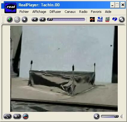
My name is Juan Carlos Rodriguez (Peluquero). and I'm from the SPAIN, San Fernando Cadiz. Well I have thank Jean-Louis for sharing the knowledge and insite with us and the world. To me the lifter projects are very exciting with prospects possibly beyond imagine.
I first built the basic lifter 1.
Weight : 3 grams
Each wing 210mm x 45mm
16mm spacing between wings
75mm tall
power aprox. 30 kv (old tv B/W) Details:
humidity ?
temperature 25°C
Thanks to Eugene for collaboration .
Click on the picture to see the video
|
|||||||||
| Envoyé via Internet | |||||||||
Hello everybody,
My name is Carl Bellmann Jr. and I'm from the USA, Edgerton Ohio. Well I have thank Jean-Louis for sharing the knowledge and insite with us and the world. To me the lifter projects are very exciting with prospects possibly beyond imagine. I first built the basic lifter then other variations of my own design that didn't work so good.
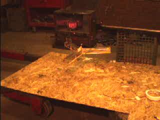
Towards controlled flight was my next goal, and it was achieved 5-14- 02 with what I call the Y-liter, because that's what it looks like. The first part of it's design was to have three wings with the alum. foil separated between each one.The emitter wire remains at full power while varying the ground to each wing, which is really three wings, it first was only two with the emitter centered above. It didn't lift itself so I added the third centered wing and it lifted and controlled very well. I am now building a balance beam to optimize a wing design. Then to make a lifter that will lift it's own power supply. Russell's 2 meter BeamShip shows me, that it can be done.
Y-Lifter specs
Weight : 8 grams
Each wing 190mm long
16mm spacing between wings
95mm tall
power aprox. 30 kv (old 19inch magnavox color tv)
The height of the flight is only about a foot because I had it
restrained with the ground wires.That would be the safe limit
until I build a better control as I let it go
higher once and it about hit me(didn't get that on video). It
can't be seen in the video but the positive lead is supported by
my cherry picker hook and has about three spirals in it down too
the top of the lifter. In the one clip you can see my hand
holding the plastic tube with ground wire attached to a brass
cabinet knob. The ground wires from the lifter are connected to
three brass eyes screwed to the inside pcv fitting oriented to my
Y-lifter.
Happy Flying;
Carl
Click on the picture to see more photos
|
|||||||||||
Hello!
I am Martin McKey Kaczmarek, from Wroclaw, Poland. I am from FNC,
Forum Nowej Cywilizacji (means New Civilization Forum) - an
experiment/research division. Earlier, we built Tesla Coil (you
can see this at: http://deuter.ing.uni.wroc.pl/~deltas/tesla.html
- soon will be there more photos "at work")
And...
I've just built some lifters and they really fly :) (of course
not all). As a power source I used a 555 generator, MOSFET
driver, flyback trafo and voltage multiplier cascade from color
TV. It produces about 25 - 35 kV. The lifters I constructed were:
First, I had some problems to "lift up" the lifters,
but now they fly really cool. I'll send you some photos soon...
There's another chance to achieve some new propulsion
techniques... And we work on this...
The next step could be a Podkletnov Effect based engine?? Who
knows...
Enjoy to lift the lifters!
best regards,
Martin
|
|||||||||||
Bonjour Jean-Louis!
My name is Mike Santoro, from Staten Island, New York.
Writing to tell you that I have successfully tested the Lifter
version 1 and am in the process of testing new designs!
I have been interested in the "Biefeld-Brown Effect"
for about 5 or so years now and am excited to finally be
experimenting!
I used a 17" Computer monitor for my power source. I plan to
send you photos and video as soon as possible.
Thanks for your inspiration and instruction!
Take care.
I will be in touch.
Sincerely,
Mike Santoro
|
|||||||||
| Envoyé via Internet | |||||||||
Jean-Louis,
Another successful lifter. (see attached)
Set up in three hours, but had to troubleshoot for an hour before
it was sustainable.
Longest flight has been 35 minute so far.
Gary Ward
Houston, Texas, USA
|
|||||||||
| Envoyé via Internet | |||||||||
Good morning Jean-Louis,
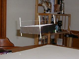
Per your Lifter Replication page, I wanted to report my successful lifter replication from last night. Attached are a few pictures of the lifter in action along with my modifications to the computer monitor power supply listed on Tim Ventura's http://www.americanantigravity.com web site that makes it more portable than an open monitor case.
Thanks,
Jeff Baker Arlington, Texas USA

|
|||||||||||||
Hi all,
I'm new to this group so I'll briefly introduce myself: I'm 28,
living near Paris, France, and I'm currently employed as a senior
IT developper.
As the subject said, I successfully replicated the Basic Lifter,
and I uploaded some pics and a video at http://lab.guerizec.net/gallery/Basic
I have some new design in mind, and I'll keep you updated when
they're ready, of course.
Have a good week-end.
David Guerizec
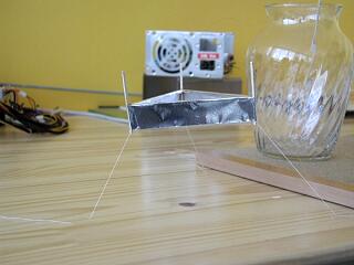
Click on the picture to see the photos and a VIDEO
|
|||||||||
| Envoyé via Internet | |||||||||
Hi !
Greetings from Norway! Excellent site ! I've finally sucessfully
replicated the lifter using a simple flyback inverter as a power
supply.
This is almost too cool to be true (I have to start rereading all
my "mad science" books).
Regards
Hans J. Grimstad
Norway
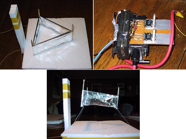
|
|||||||||||
Hey :-)
Finally at last, got one to fly, it might look a bit shonky, but
it works well.
I call it the X Wing, i dont think ive seen one exactly like
this one.
Hope your all haveing a good day/night
Bye
Nick.
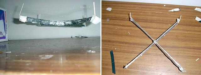
|
|||||||||||
Jean Louis,
I am glad to announce that today I successfully replicated your lifter 1 Design over here in Belgium
I made some modifications to the dimensions based on the successes of other lifter designs. As a next step, I plan on experimenting using other shapes, trying to enlarge the path of the field lines.( if insulation would seem to be possible, try to have 2 intersecting lifter stages) The flight was somewhat unstable, but it clearly lifted.
You have done a very good job on your website! Keep up the good (scientific) work!
Kind regards,
Hans
Ameel
Kortrijk, Belgium
|
|||||||||||
| Envoyé via Internet | |||||||||||
Hi Lifters!
Applied Electrogravitics strikes again with the new,
unbelievable and exotic 6-foot (2-Meters!) Beamship Variation
III. Just look at the photos!
I almost would not have believed something so big and heavy could
degravitate with such astounding upward force with such low
power!
It is SO impressive and awesome in flight; the pics and video
don't do it justice. This technology CAN be scaled up with no
limit yet in sight!
Except now, to build larger Beamship series electric spacecraft,
Applied Electrogravitics is forced to find larger facilities.
Say, an abandoned aircraft hangar in SE Pennsylvania (TT Brown
Territory).
Beamship is equipped with full space-frames, SEARL IGV-style landing gear (they are designed to/can support Searl's multi-ton IGVs), uncovered saucer framework. This is my favorite spaceship yet, and, its much quieter. Looks real impressive on floor and in flight! Full frames and cabin, ready for covering with mylar, etc.
Beamship Variation III - Specifications |
| Weight: 42 grams Width: 6 feet on each side (2 Meters) Height: 18 1/2 inches Anode wire: #40 Stainless Steel Wing foil height: 2 inches Spark gap: 2 3/4 inches Ambient temperature: 71 degrees F. Amb. relative humidity: 68 % date: sunday, May 12th Timestamp: 1:55 pm EDT Beamship is weightless at: 30,000 Volts straight DC @ .85 mA current. That's about 25.5 Watts. |
Beamship Variation III is in a stable neutral hover 4 1/2 feet off the lab floor at: 35,000 Volts (35KV) @ 1.35 mA current. That's 47.25 Watts for a 2-meters (largest ever in the world - call Guinness), 6-foot wide scale model electric spacecraft. Still has plenty of upward thrust at full power.
Will test for payload, but my best guess is 4-5 grams payload at 1.5mA @ 37KV.
The bar has been raised, and Applied Electrogravitics adds yet an even larger and better Beamship to its rapidly growing space-fleet. This is a nice size for onboard power and radio control. Look at my single-channel outboard RC, hooked up to power supply. Not much, but its a start... just neet to add 3-more channels for full RC. Ciao, fellow space-lifters, we are in the final space age...
Russell
Applied Electrogravitics

Click on the picture to see the photos, details and VIDEOS
|
|||||||||||
Hi Jean Louis
I have finally got a lifter1 to fly! I have built numerous
versions but all were too heavy to take off. I found that if i
suspended them sideways I could see that they were generating a
little thrust.
my successful lifter was a 20cm equilateral triangle. I folded
the foil over and didn't have any balsa wood under it (this made
it very weak but it could still hold its shape). the upright
struts were about 0.5mm square balse wood and the wire was very
thin copper wire pulled from some other wire, suspended 4cm from
the foil.
the power supply is an old 14" monitor giving 22-24KV.
I have not yet taken any photos, but hopefully will have some
soon.
loaction is: Palmerston North, New Zealand. latitude 40.2 S,
longitude 171.8 E
thanks for all the info on your web site.
Andrew Murphy
|
|||||||||
| Envoyé via Internet | |||||||||
HERE ARE PHOTOS OF THE FANTASTIC 3-FOOT DIAMETER BEAMSHIP
VARIATION I AND THE EVEN MORE INCREDIBLE BEAMSHIP VARIATION II.
BEAMSHIP VARIATION I USES #35 ENAMELED MAGNET WIRE AND EMITS A
SLIGHT HISSING SOUND IN FLIGHT.
BEAMSHIP VARIATION II IS A GARGANTUAN FOUR FEET IN DIAMETER
AND HAS LANDING PODS AND USES #30 MAGNET WIRE. VARIATION I IS 17
GRAMS AND LIFTS A PAYLOAD OF 6 GRAMS AT 1 mA AT 40KV STRAIGHT DC,
VARIATION II I HAVE NOT ADDED A
PAYLOAD CABIN AND SUPERSRUCTURE TO YET, BUT AM SWITCHING TO #50
STAINLESS STEEL MAGNET WIRE FOR NO NOISE AND EVEN MORE LIFT! I
HAVE EXTERNAL SINGLE CHANNEL (MAIN LIFT) FOR BOTH (HAVE A PCM
COMPUTER RADIO XCEIVER MODULE ATTACHED TO POWER SUPPLY) SO I CAN
CONTROL FROM HALF A MILE AWAY, AND THEY GO FROM THE FLOOR TO THE
CEILING AND CAN HOVER REALLY STABLY AT ANY ALTITUDE.
THE THRUST IS TREMENDOUS! I USE A GAMMA HIGH VOLTAGE RESEARCH
POWER SUPPLY WITH CURRENT LMITING FROM 0 TO 1.5 mA, AND VARIABLE
VOLTAGE FROM 0 TO 40,000 VOLTS. wITH SQUARE WAVE PULSING, CAN
LIFT U TO FOUR TIMES THE PAYLOAD I
CURRENTLY ENJOY. CIAO STEVE AND ALL MY FELLOW LIFTERS!
Russell
Applied Electrogravitics
Click on the picture to see the photos and details
|
Dear M. Naudin,
On april, the 21st, 2002 I had my successful replication of the
lifter 1 experiment. The lifter hovered very stable.
The HV supply was made with a 14 inch color monitor.
With best regards,
Carsten Spanheimer, Tuebingen, Germany.
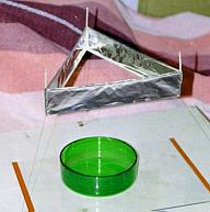
Click on the picture to see the photos and details
|
Hi Jean-Louis,
I've successfully replicated the Lifter1 - thanks for your
instructional web pages! I've put together a web page at http://www.zikzak.com.au/zik/lifter/
describing my experiences. Feel free to reproduce the photos from
there if you like. There's also a rather poor quality MPEG video.
Next I'm going to look at making a lightweight AC power supply
suitable for use with a flying model. I'm also interested in
trying to detect mass loss or positive charging in a closed
system to attempt to verify that electrons are acting as reaction
mass.
Zik Saleeba
Melbourne, Australia
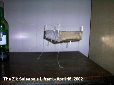
Click on the picture to see the photos and details
|
Tout à l'heure, avec un exmoniteur vga, et
l'aide de vos très claires explications, j'ai fait décoller, du
premier coup un Lifter de 20x20x20.
Bruissement, odeur d'ozone et très nette perception d'un flux
frais émis par l'appareil.
Bien entendu j'ai respecté les mesures de sécurité
indispensables et n'ai eu aucne surprise, sauf une : ca vole!
J'avais découvert votre site il y a quelques mois lors d'une
recherche sur les microondes et il m'a été à nouveau signalé
par ZZZ ,
Félicitations et merci pour la pédagogie du site et pour toutes
les questions que pose cette manip réussie.
Matthieu Filippi
Afa. Corse du sud

Click on the picture to see the photos and the videos
|
|||||||||||
| Envoyé via Internet | |||||||||||
Bonjour, M. Naudin!
Here is a picture of my wildly successful third lifter and my website ( http://64.133.223.115/physics/ ) with all the details. I have to thank you for leading us in this endevour and compiling all of the information.
Keep up the great work!
Ben Nesbitt, Bellevue Washington
|
|||||||||
| Envoyé via Internet | |||||||||
Bon Jour! Thank you for the great information. It has been
quite inspriational.
I recently replicated your rotolifter experiment (with just one
lifter - simpler). My model making skills are lacking, so the
lifter was too heavy, but tests have got it to spin at 80-100
RPM.
I've also had some success with the designs involving a metal
cylinder and plate and the one using two cones. Neither fully
rotated on the test stand (reference my model making skills) due
to the large friction. More information will be coming once the
rotator arm is improved and more designs get tested.
Attached is a video of the rotolifter experiment.
Here is the information for your log book:
Wesley G. Faler
Ann Arbor, Michigan, USA
Roughly: Latitude: 42°10' N
Longitude: 83°26' W
Thanks again!
-Wes

Click on the picture to see the photos and the videos
|
|||||||||||
Hi all lifters,
Today I successfully flew my RC lifter using helium balloons to
just balance out its weight. The motorised panel worked as
expected.

Click on the picture to see the photos and the videos
Enjoy it!
Regards,
Saviour.
Lifter replications Log Book : Previous Page - Next Page
Return to the Lifters Builders page