The
Lifters successful replications
Experimenters
Log Book
created
on October 10th, 2001- JLN Labs
All informations in this page are published free and
are intended for private/educational purposes and not for
commercial applications
Lifter replications Log Book : Previous Page - Next Page
|
|||||||||||
Hi Jean-Luis,
Thanks for the excellent instructions on how to build the
lifter! After a few turkeys that are too heavy to fly, finally
the 4th one with 9 cells took off, totally fascinating!It is
powered by a 14" color monitor. The flyback circuit I made
does not seem to provide enough current.I have no cameras so I
can not show the picture, sorry.
Here is some specifications of my lifter:
-9 cells, triangular lifter frame, each side of the unit triangle
is 160mm, from plastic drinking straws of 5mm diameter x 180mm
long.
-bamboo-made toothpicks as wire posts(which I boiled in wax
except 10mm from one end before use to prevent burn-up), 2mm
diameter x 60mm long. wire is
approximately 0.2mm dia.
-Aluminium foil 30mm x 150mm ( 9)
-Superglue (cyanoacrylate)
Construction tricks:
-Glue the foils to the straws 250mm from one end. roll the foil
around till it cover half the diameter of the straw. Glue the
rest of the foils to the straw WITH
THE SAME FOIL-STRAW ORIENTATION.
-Squeezed the 250mm foil-free end end of straw 2 and insert it
into the 50mm foil-free end of straw 1, then insert the 250mm
foil-free end end of straw 3 and
insert it into the 50mm foil-free end of straw 2...WITH THE SAME
FOIL-STRAW ORIENTATION.
-You should have now a strange looking "pole" of straw
and foil "flag". Lie it dow flat,join all the gaps
between foils except the 2 ends with litle piece of
foils with sticky tape, makde sure they are conducting.
-By bending at the 200mm + 50mm junctions in a particular way,
the final lifter shape is obtained.
THIS IS BEST EXPERIMENT BEFOREHAND DONE WITH A BARE STRING OF 9
STRAW TO SEE WHICH WAY THE WHOLE THING BEND.Glue certain joining
corners with glue to hold the shape. Squeeze and join the last
straw-straw juction, and tape the foil together as before.
- Take the toothpicks and piece the straw at/near the
apex/corners with the un-waxed end.Glue them to the frame. String
the wire, glue on the 3 legs at the 3 outer corners and you are
finished.
Cheers and Happy Experimenting
Vinny Lam
Melbourne, Australia
|
|||||||||||
Hi Jean-Louis,
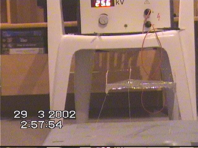
I successfully replicated lifter 1 using a 0.5mA current limited
25kV DC high voltage power supply.
Now I am working on a more elegant and precize variant using
simple aluminium foil and 0.10 mm diameter steel wire.
I assume we need a perfect DC HV output signal generator to begin
experiments with harmonic ion-acoustic frequency chords a la
Keely. But how can
we most efficiently couple some frequency generators to the HV
signal output?
Please find some pictures of the first flight uploaded at
http://www.geocities.com/hizlimurat/lifter1.jpg
http://www.geocities.com/hizlimurat/lifter2.jpg
http://www.geocities.com/hizlimurat/lifter3.jpg
http://www.geocities.com/hizlimurat/lifter4.jpg
You will also find some videos there but you need a Divx MPEG-4
(fast motion) Codec reader to see the movies in your real player.
See for it on your DVD
driver CD.
http://www.geocities.com/hizlimurat/lifters1.avi
http://www.geocities.com/hizlimurat/lifters2.avi
http://www.geocities.com/hizlimurat/lifters3.avi
http://www.geocities.com/hizlimurat/lifters4.avi
Best regards,
Berkant
| (048) |
|
||||||||||
I made these about 3 months ago and at present I'm working on minaturizing the power source,heating the cathode ( possibly to incandesance using tungsten in a vacuum ), testing lifters in SF6 or freon R-12.
I'll write more when the results are in but in the mean time,
Thanks for posting all this info...towards optimization.
Dan

Click on the picture to see the photos
|
|||||||||||
Dear Jean-Louis,
On saturday the 9th our group did 2 experiments which we would
like to share:
- Lifter flight in a closed box :
To clear the question for us wether a lifter would fly in a
closed box or not, we used an (empty and dry) aquarium(of glas)
of the dimensions:
H375mm x L775mm x B330mm.
The top of the aquarium was closed with a piece of wood with 2
small holes for the cables.
The results were that the lifter 1 flys as allways if not placed
to close to the walls of the aquarium.
We made a short video about this flying tests(320 x 240pixel with
a MC3 from Kodak. We recommend this cheap mini-camcorder from
Kodak, its really great !!)
- Flight video of Lifter 1 :
With our new mini-camcorder MC3 we made some small flight-videos of lifter 1.

Click on the picture to see the videos
Mit freundlichen Gruessen,
Stefan Kaechele
Laufenburg
Germany
|
|
||||||||||
Dear Jean, this is Tony Klose again.
The science fair at my school was a success!!! Guess what...
I won the first place prize in the seventh grade, and the grand prize over the whole school using the Lifter1 !!! I am so happy and I wanted to thank you for everything.
Thanks SO much!!!
Sincerely,
Tony
Klose
|
|
||||||||||
Dear Everybody:
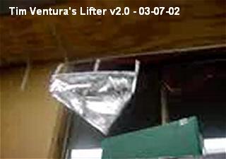
This is a test of the lifter version #2, which contains an internal support-structure consisting of an additional 3 lifting surfaces. Essentially, it's one of the lifter V1 models placed inside an identical model of a larger lifter.
The power-output seems to be a little bit higher, and it is definitely more unstable on it's tethers. This could simply be due to weight-distribution issues from my construction or it could be something else entirely . . .more power, tether length, etc..
Thanks;
Tim Ventura
Click on the picture to see the photos and the videos
| (045) |
|
||||||||||
Dear Jean-Louis
Thank you so much for your assistance with my dysfunctional lifter.......
I made a few changes to it today and it now lifts off !!!
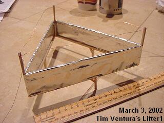
I'm not using tie-downs on it yet, so it currently doesn't do a whole lot (takes off, loops the wires, arcs, and drops), but I've tried using a guide and it climbs right up it -- at least 8 inches high (the plastic guide is only a foot tall -- and I'm holding it with my hand on top!)
Click on the picture to see the photos and the videos
Here is a lifter test-video that I took this evening. I used black tie-down threads on the table surface and the 14" computer-monitor for power. It levitates perfectly...!
Tim Ventura
|
|||||||||||
Good day
just to let you all know ... I have updated my lifter site www.eccdm.d2g.com
NEW Feb 23 2002 : The first stage of the rocket lifter. This lifter uses a plate in stead of wires for the plus side of the HV.

Click on the picture to see the photos and the videos
I am working with a lifter that does not use wires for the plus side of the HV...instead I am using a plate. The design can be built to use multi stages if needed or arranged like the SFPT thruster.
Gaetan Masse
|
|||||||||||
Hello.
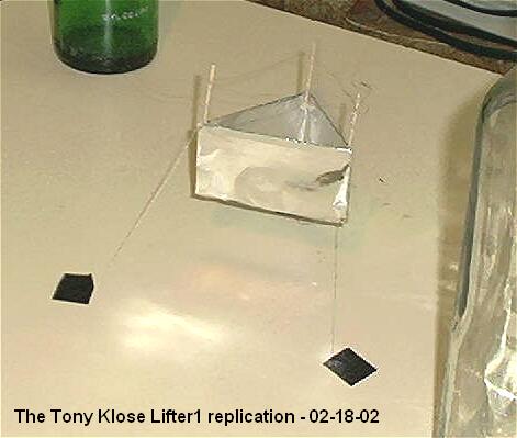
This is Tony Klose again. I made 6 different versions of the Lifter 1 and two of them worked. One works really good and the other justworks a little bit. I have attached some photos of the better one.
Specifications:
It has an upper frame of balsa that is 80mm long and about 1 1/2 mm wide. I cut the balsa from a big strip of it. The tin foil is one long piece that goes all the way around the craft. The positive electrode is really thin copper wire that I took out of a regular cord that plugs into the wall. The TV that I am using is old, but it still gives enough power. I don't know how many Kilo Volts there are though. The vertical sticks are made of thin balsa. It is a small lifter but it is really cool. Im going to use it in my science fair at school. I also don't know what it weighs, but it is very light.
My location is Shawano , Wisconsin. I don' t know what the latitude and longitude lines are though, but it is in north east Wisconsin. Well, good luck. I will inform you of any updates.
Best regards,
Tony Klose
Click on the picture to see all photos and details
|
|||||||||||
Here's another one for your page:
today i built and tested lifter v1.02 (third lifter 1 attempt)
design parameters as follows:
150mm wide on each side
30mm wire gap
25mm foil hight
1cm legs on bottom
this time i ripped the 5mmX3mm balsa in half length wise to yield
~2.5mmX3mm
balsa rails to reduce wieght
i glued foil over the top of each arm like jln's ufo lifter.
turned on power
one side went up
i shut off the lights and looked to see where the corona was
leaking
i added a little black tape to the corners and moved the negative
electrod to the center of the foil instead of the corner
im happy to report that i finally have a fully functioning
lifter.. it was great. my family got a kick out of it..
especially my dad lol..(suggested trying to lift the table as a
later goal lol)
one thing tho.. it arched pretty often, even when it was floating
pretty stabley. my mom thought it was fantastic how it arched
like that in the air.. it looked really marvelous, tho
undesirable.
thank you guys for the feedback. it really solidifies the reality
of the technology when you see it in action for your self..
may the lifting force be with you (stolen from jean-louis
<GRIN>...i'll pay royalties, i swear...lol)
Mike
|
|||||||||||
Here's another one for your page:
I must say I was amazed at how totally simple it was to run this
experiment, thanks to the excellent information on your website.
- Ed Hutchins

Click on the picture to see all photos and details
|
|||||||||||
Success at Last! Persistence does pay off. Mike and others, don't give up.
Finally received my new digital scale (which I ordered over a month ago). When I weighed my old, patched up lifter, it came in at 7.6 g. No wonder I could never get that turkey to fly. It was built to JLN's specs. I even used smaller balsa wood, than specified, so I thought it would be lighter than JLN's. Of course each time I modified it, or patched it, it kept getting heavier. I still don't know how JLN got his to be so light: only 2.3 g. Maybe they have lighter balsa wood in France:-) Or, maybe I used to much super glue gel.
So, out with the old and in with the new. New lifter uses 3 mm diameter x125mm long, light weight plastic straws (actually coffee stirrers) for top foil frame. The straws are much lighter than 2x2mm balsa and already have the rounded shape for the foil top. The lifter is slightly larger than JLN's Lifter 1. It is a 230 mm triangle, due to the length of the straws. It weighs about 3.8 g. I was afraid that it wouldn't fly, since it exceeds the total weight of JLN's Lifter 1 plus payload. However, when powered up by a 15" computer monitor, she leaps into the air! Success at Last!
I had my tie downs arranged differently than most. I had 3 strings from each leg that were tied together at some point, with a single string going down to the table top. My lifter flew to the top of the string, then apparently due to some asymmetry in thrust, she slowly veered over to the side until the thrust was more sideways than vertical, and then she promptly fell on her side to the table. Changing the tie downs to the more common one string per leg corrected this problem and now she flies straight and true just like in the videos. I think that this demonstrates to all those who say that lifters are unusually stabile that this is not true. The stability comes from the tie downs, not the lifter itself.
Now, I just have a little arcing problem that I need to correct. When it arcs, the lifter immediately falls to the table.
Construction Details:
New lifter uses 3 mm diameter x125mm long light weight plastic straw (actually coffee stirrers) for top foil frame. Not all straws are lighter than balsa wood, choose your materials carefully for the lightest weight. If you don't have a scale, you can compare the relative weight of your materials by making a crude balance by balancing a piece of balsa across something round, like a pen. Then place an equal length of balsa or straw at the same distance from the pivot point, it should immediately become obvious which material is lighter. Use the lightest material that has sufficient strength to do the job. Wash your hands before working with balsa vertical supports, since finger oils can make balsa conductive enough to catch fire.
Construction of the frame is a piece of cake. Make a single lengthwise slit 1cm long in one end of each straw. Close up the slit end and insert it into the open end of the next straw, along with a drop of gap filling super glue. Make 3 pairs this way, then line up all 3 pairs side by side and use a ruler or such to bend the straws all in the same place.Close up the slit end of each pair and insert it into the open end of the next pair, orienting the bends, until you have a triangle. Glue if desired.
Don't use a bottom frame, it is unnecessary weight.
Next cut a long strip of aluminum foil 4cm wide. Put a bead of gap filling super glue along the outside of one side of the triangle. place it on the foil 1cm below the foil edge and leave some extra foil at the end. Hold firmly until the super glue sets. Use an Exacto knife to remove a small rectangle of the upper 1cm foil to allow clearance for the corner post. Apply super glue to the next side of the triangle and then roll the fame around and press it against the foil as before. When you reach the last corner, leave a 1cm flap of foil to wrap around the corner and glue to the other foil. Place another bead of glue along the inside of the 1cm foil edges and roll over the top of the straws for a nice rounded edge.
Vertical supports are 3 pieces of 2x2mm balsa wood 11cm long (should have made them longer and cut to length after gluing - one got glued in the wrong place! Vertical support acts as both legs and wire support. You don't have much to glue the vertical supports to, except the foil. You will need another balsa support temporarily inside the foil corner to support the foil during gluing. Make sure this support is treated with some kind of lube or something so it doesn't get accidentally glued to the inside of the foil. Mark the balsa supports 4cm from one end, apply super glue to the supported foil and attach the vertical support with the line even with the foil top and the 4cm sticking in the wire support direction. Squeeze the foil between the to balsas until the glue sets. Repeat for other corners. Allow super glue to set over night before attempting to install the wires and tie downs. Always allow super glue to set overnight before testing to prevent fires.
Check the weight of your lifter. If you don't have a scale, you can use the crude balance technique as described above. A US dime weighs about 2.2 g. JLN's Lifter 1 weighed just over 1 US dime. Mine at 3.8 g weighs a little less than 2 dimes, but it is slightly larger. If your lifter is not in this range, you are likely to have a problem getting it to fly. I realize that this only helps if you happen to have US dimes. Maybe others can give the weights of similar coins in other currencies, to help those who don't have scales.
All for now,
John
|
|||||||||||
Hello Jean-Louis
BB Racer photos...
Click on the picture to see all photos and details
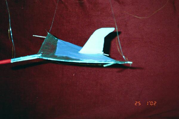
Here are the BB Racer photos, built exactly the same as the lifter but in the horizontal plane and suspended from the ceiling. Tissue paper is used to fill the back half of the racer. Because it travels at 4 metres per second the BB Racer needs to be reasonably aerodynamic. The nose is a plastic needle this is to add a bit of weight to hold the nose down!
Lifter Photos.......
My lifter is a replication of JLN's and works very well.
Good experimenting, all the best
Neil McPherson.
|
|||||||||||
Dear Jean-Louis,
Bonjour M. Naudin,
Ma gratitude pour votre site et votre travail. Vous êtes une source intarissable.
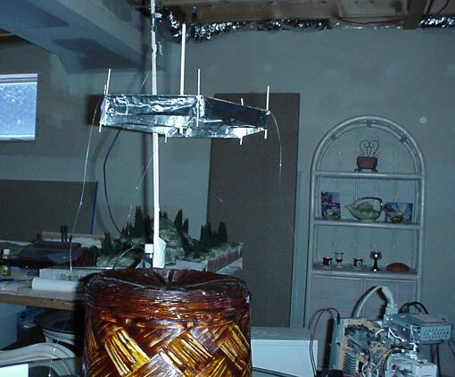
De ce pas je vous envoie une photo d'une réplique en fonction du modèle HCD-03 de M. Claude Dupré.
Pour moi, la prochaine étape consiste en l'accumulation de métrique sur un des élements de base soit, un fil et une plaque, afin de batir une théorie d'ingénerie. J'ai le but de maîtriser la combinaison des variables évidentes : dialectrique, champs de force électrique, voltage, fréquences, capacitance et géométrie d'agencement.
Encore une fois, merci...
Cheers
Serge Deragon St-Basile-Le-Grand Québec, Canada
|
|||||||||||
Dear Jean-Louis,
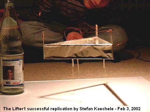
our working group was able to replicate the lifter 1 experinent
succesfully.
Details:
humidity 38%
temperature 20°C
High voltage supply is a EHT multiplier(from a university) with a
max. of 50KV pure, not pulsating DC, voltage finetuning, change
of polarity, and scales for the actual OUTPUT voltage and
current. current up to 2,5mA.
Device was lifter 1 with adjustable wire and weight of 3g.
The shapes of the top part of the foil were mostly very well
rounded !
wire CuL with 0,16mm diameter
The wires from the high-voltage supply were partially covered by
teflon.
Results:
--------
lift-off voltage with 31mm wire distance was 18KV and a current
of 250uA
lift-off 25mm
15-16KV 250uA
lift-off 20mm
14KV 450uA
polarity on the wire in all 3 cases was minus !
weak hissing sound.
if you start calculating the lift-off power is between 2,2W/g and
only 1,3W/g.
AND I think the loss current can be calculated as about 200uA, so
the real force for the lifting effekt would be in the cases
above only about
250mW/g
we did a video of the lift-off and if you want I can send a
picture of the high voltage power supply connected to an
oscilloscop.
Mit freundlichen Gruessen,
Stefan Kaechele
Laufenburg
Germany
Click on the picture to see all photos and details
|
|||||||||||
Hi Jean-Louis,
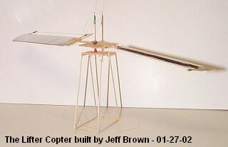
Jeff Brown asked me to send you pictures of his lifter
helicopters (while he gets some sleep). They're a little
unstable, but they fly!
Click on the picture to see all photos and details
|
|||||||||||
Hi JLN,
I'm was impressed with your work on you site since 1996-7, when I see it for first time, and I'm very grateful for all you effort on every experiment, test, etc as it must take a lot of time (and money) thanks you!
Today I was testing another configuration for the lifter (see
pic below). It has 5 basic cells, spaced 2 cm, plate is 3 cm tall
x 15 cm cocking aluminium, wire is thin nude copper 3-3.5 cm
above the plate, frame of balsa wood. Flyes very well, very
powerful compared to the triangle lifter (that I build first, see
photos), but a bit unstable.
Power supply was a DC (how do you pulsed the HV??), flyback, 2 x
3055 and tripler type, connected to around 30v.
HV was 30kv I think (sparks very bright of 3 cm), I don't take
measuraments to it, nor at the weight.
All pics are of the unconnected device. There are movies if
someone ask, drop me a line.
Thanks again, Juan Barrios, Buenos Aires, Argentina (latittude 34, long. 58) :-)
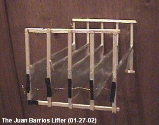
Click on the picture to see all photos and details
|
|||||||||||
Hi Jean-Louis Naudin,
We finally got a lifter to fly.
The project is based on "Lifter 1" web page.
The lifter is buit of balsa tree(~2 X 2mm) and the copper wire is
about 0.25mm thick. We used an old 14" monitor (24kV) as
power supply.
We noticed that the lifter couldn't fly if we started from the
floor. We had to place "legs" under it to raise it
20mm..
The gap beetween the copper wire and the foil war reduced (from
org. 30mm) down to 28 - 26mm, this beacuse of the low power
supply.
We suppose that the lifter would have flown better if we had a
power supply higher than 24kV.
But anyway...it worked!
Greetings from North of Sweden (Umeå)
Magnus Tjällgren and Pontus Pursiainen, University of Umeå
|
|||||||||||
Dear Jean-Louis Naudin,
Hello! I have been out of touch for several weeks. But I
wanted to let you know I have constructed 13 lifter frames; of
them, numbers 7, 11, and 13 have flown. The 13 is
nearly a meter across!
I still don't have a scanner, but as soon as I do I'll send you
some photographs.
Speaking of photographs -- I've made many HI8 movies of the
devices in flight. On one recording -- taken in my garage,
after sundown, with dim illumination -- I noticed a peculiar dark
band running from the wire to the upper edge of the foil. It
persisted throughout the video, was invisible to the eye (I could
see it only in the recording), and I've not been able to
reproduce it. I wondered if you'd ever seen anything like that.
At any rate, my 14" PC monitor power supply is still
working, and I have many more frame designs to test. I'm using
3/16" balsa wood from the
frame, and aluminum foil for the vanes, and I finally found a
spool of loudspeaker wire with very fine gauge shielding wrapped
around the conductors -- 35 or 40 gauge, I think. It takes
forever to unwind, one strand at a time, but it makes excellent
lifter wire.
That's all for now. Good lifting, my friend!
Frank Tuttle
USA
|
|||||||||||
Hi guys,
Today I have tested and confirmed that vertical stacking works
very efficiently, and is quite easy to implement. This is how I
did it: Starting from top is the anode fine wire, then 40mm below
is the foil, following are a number of stacked foils with the
same 40mm separation between them. No wires in between as the
sharp lower edge of the foil acts as a fine wire. Make the top
part of each foil as smooth and round as possible and the lower
as sharp as possible.
Connect the positive to the top wire and loop the positive
skipping one foil at a time. Do the same for the negative
starting from the top foil and ending at the lower foil.
Preferably you should have an odd number of foils so as to end up
with the highest and lowest foils negative. A 3 stacked basic
lifter lifted 8g whilst a 2 stacked Dupre type lifters (weighing
8g lifted 18g!!, I should add another stack to this, possibly
providing about 28g lift or maybe more. For this
lifter I am using 50mm gaps and about 40Kv or a bit more. Lift is
being calculated by adding weights in a plastic container glued
in the centre. Weights used are pieces of thick wire cut to weigh
0.5g each.
Saviour.
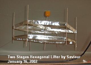
Click on the picture to get more details
2 vertically stacked hexagonal lifter. 1/2 Kinder egg (0.5g) on top used as container for loads. Air gap between foils is 50-55mm, foil is 20mm each. Note round smooth edge on top side of foil and sharp edge on lower side of each foil. Note that leg supports are not decorative, they are necessary to minimise field effects between the lower edge of the lower foil and the table, even if used on an insulated base. This lifter weighs 11g and lift an additional weight of 19g including weight of container. Top wire and bottom foil are positive (connected together), the middle foil is negative.
See more photos and technical datas at : http://bel.150m.com/
|
|||||||||||
Hi Jean-Louis,
You can add 53N latitude and 113W longitude (Edmonton Canada) to
your Lifters map, if you like.
I finally got a lifter to fly. I built a balsa frame according
to the dimensions on your "Lifter 1" web page, except I
allowed room for a greater separation between electrodes. I still
don't have a supply of fine wire, so I used 0.25 mm bare copper
wire for the anode. I first tried an electrode separation of 38
mm and wrapped a single sheet of aluminum foil (650 x 40 mm)
around the frame for the cathode. The leakage current was too
high, probably due to the sharp leading edge. There was no
measureable thrust (less than 0.3 g) and very little electric
wind. Next I cut a 650 x 45 mm piece of aluminum foil and I
"gently" folded over the top 5 mm of the foil (i.e. no
sharp crease) and this time, the lifter skidded across the floor,
but failed to lift off. I moved the aluminum foil up until the
separation was 36 mm, and finally it lifted off. The leakage
current was still very high, but could probably be reduced with a
greater radius of curvature on the leading edge of the cathode.
Regards, Mike Ady
|
||||||||||
I have been waiting for this moment for months now,
I have FINALLY achieved success with my lifter. After weeks of
troubleshooting such a simple design, I got my lifter to lift
off. What an amazing feeling.
Flight is very unstable, but VERY cool to watch. My mom loved
it.
A very heartfelt and sincere thank you to Jean-Louis Naudin, This
would never have been possible without you. Also thanks to
everyone else in the group who was willing to help a young
amatuer like me out.
Good luck and fair travels to all,
James
|
|||||||||||
Dear Jean-Louis
I am sending to you pictures of Lifter 1 replica.
Experiment was succesfull. At first there was problems with
discharge between electrodes, but after aplying oil on the wire
and foil edge discharges stoped.
Lifter specification:
Edge length 150mm
Weight 1.4g
Height 100mm
Foil width 40mm
Distance between wire and foil edge 33mm
Wire diam. 0.25mm
Supports made from balsa
Powered with ViewSonic 14 monitor
Best regards
Andrejs Pukitis
Riga,
Latvia (Lettonia)
|
|||||||||||
Dear Jean-Louis Naudin
I was impressed deeply by your great work!!!
So, I tried the replication experiment.
I used the lifter1 design. And I made the about 40kV HV power
supply using by 15kV, 20mA neon transformer and voltage doubler
circuit. The resistor used in the circuit in order to prevent arc
disahrge between two electrodes on the lifter1.
The experiment was successful and I'm very pleasure!!
I'll send you more results later.
Sincerely yours.
Happy new year everyone!!!
Jung-Seo Park
http://ironrose.soongsil.ac.kr
jspark@ironrose.soongsil.ac.kr
js_park@hanmail.net
|
|||||||||||
Bonjour Monsieur Naudin.
Just wanted to inform you that we managed to get a successful
lift off of a Lifter version 1 using a 24 KV power source on
December 22. We had to raise the positive wire to a height of
40 mm due to arcing. This was probably due to humidity in the
room at the time. Though lift was unstable it was definite
lifting to a tethered height of approximately 1 foot above the
launch surface. Construction was to Lifter 1 specifications using
a single sheet of foil for the capacitor, 40mm in height, three
straws for the frame with three coffee stir-sticks as the support
struts for the positive charge wire. The Lifter only lifted on
two sides until we moved the ground to a position diametrically
opposite to the power source connection to the lifter.
Currently we are looking to increase our power source capability
before continuing with our experiments.
Here are the photo's of our first lifter flight test of December 22, 2001 as mentioned. Please feel free to post them. Since then we have had several more succesful tests using smaller lifters of approximately 120mm per side. We hope to use these as the basis point for testing various configurations. Rather than use three tether lines we rigged a guide line through the centre of the lifter and used a single line as a tether in order to reduce weight. Another method we considered using was to attach two guidelines to the ceiling at a slightly greater width than the lifter and attaching it to the launch surface inside the Lifter itself. Thus as the Lifter rises it will eventually slow itself down to a height based on on the angle of the two guide wires. Though this causes some stress on the frame it does allow for a lower take-off weight and thus a lower level power source can be used.
Regards,
Bruno Tilgner
|
|||||||||||
Hi,
My first working lifter is based on the Keops1 from Stéphane Bernard.
The pic can be found at http://earth.vol.com/~lostroad/l1.htm
Lifter replications Log Book : Previous Page - Next Page
Return to the Lifters Builders page