The
Lifters successful replications
Experimenters
Log Book
created
on October 10th, 2001- JLN Labs
All informations in this page are published free and
are intended for private/educational purposes and not for
commercial applications
Lifter replications Log Book : Previous Page
|
|||||||||||
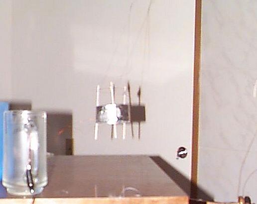
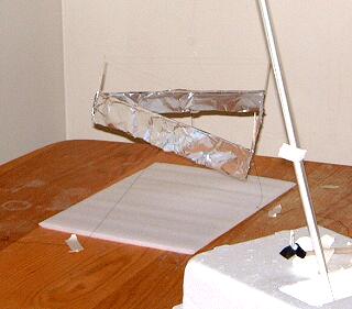
I've made a simple low-power design. Cylinder
with 3 drink stirring straws to hold the thin wire at a distance
of nearly 40mm(the air is moist and conductive in Washington,
needed some extra distance to prevent arcing.) above the foil,
which was formed on the end of a tall cup to have an inward curl.
The whole assembly would pull towards the ground wire, even the
length of wire that was en route to the device. I suspended the
frame with thread to the ceiling, and then tied it away from the
ground wire(no more crashing into it and arcing!). Now we get
the lifted effect you observe in my pic =]
it's kinda fuzzy, I'll have to send you a better picture sometime
soon, maybe with a better device as well =p
Happy Holidays ^_^;
-Shanjaq

|
|||||||||||
Hello all,
I constructed a small cylindrical lifter using aluminum foil
drinking straws, and copper magnet wire. The cylinder is the same
diameter of a cardboard toilet paper roll. The drinking straws
are the type that come with juice boxes. The cylinder is 2.5cm
high. Taped to the cylinder are three sections of straws. Taped
to the straws is a loop of copper magnet wire. The wire is just
under 2.5cm above the aluminum cylinder. The power supply is a
100kV generator powered by a 12V security system battery. I
estimate that the generator is actually putting out just over
20kV, based on the fact that sparks can't jump a spark gap
greater than
about 2.5 cm. When I switch on the power supply, the lifter
quickly lifts to between a half centimeter and a centimeter off
the table and floats around a bit. When I switch off the power
supply, it falls back to the table. I believe that the weight
and/or stiffness of the charging wires is preventing it from
lifting higher.
I am very excited, as this is my first lifter to actually fly. Also, it requires only 12 WATTS!

Here is the link to my 12 watt lifter page:
http://www.imagineanything.com/energy/projs/lift01.htm
Tony
|
|||||||||||
Hello Mr. Naudin,
Here are a couple of pictures in black and white of the lifter I
built this week end.
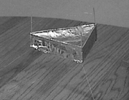
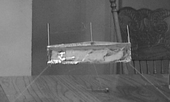
Thanks for the info on the spark gap.
Best Regards,
Andy Alcon
Fort Worth, Texas
|
|||||||||||
Chers Jean Louis
Je reprends contact avec toi afin de dire que j'ai créé un
nouveau type de lifter .
Je l'ai nommé le Keops 1 je te laisse imaginer
pourquoi ...
J'ai voulu augmenter la poussée du basic lifter ce qui m'a
amené à créer cette nouvelle forme ...
Keops a décollé hier soir vers 22h30.

Keops utilise les dimensions du basic lifter soit
12 cm de coté construit une pyramide à 3 coté fil de cuivre à
3 cm comme pour le basic. Au sommet de la pyramide construit une
petite boule d'alu connectée au +, secouez le tout, mettez sous
tension et hop IL VOLE !!!!! :-)
Voila, j'ai pensé a cette structure pour que la poussée
produite par les 3 cordons converge vers un point ...
J'ai ajouté la sphère d'alu afin d'augmenter le
"stress" en ce point...
Bon courage Jean Louis
Cordialement
Stephane BERNARD ( FRANCE )
Click here for more informations about the "Keops1" Lifter
|
|||||||||||
Hi,
I successfully replicate lifter v1.0. I am sure that my Prof.
will be very interested to see it on Monday.
A few of quick and dirty experiment gave the following results.
------------ experiment #1 ------------
Conclusion:
The voltage required to take off (lift) by itself is bigger than
what is required to keep it afloat.
Experiment:
- Set voltage to minimum, turn on power supply, the lifter
does not take off.
- Slowly increase the voltage, until the lifter lifts
- While it is in the air, slowly decrease the voltage.
But the lifter will still be afloat, even if the voltage is
below what is required to take off.
----------------- experiment #2 --------------
Conclusion:
If the voltage is too low for the lifter to take off by itself,
you can blow light wind (from your mouth) to induce the lifting
process
Experiment:
- Set voltage to the level that is required to keep it afloat
(from experiment #1). Turn on the switch, nothing happens.
- Blow light wind, the lifter moves side way and the go straight
up.
---------------- General Setup -----------
Power supply: PC Monitor (Sampo Alphascan 15)
Lifters: Version 1.0 from Jean-Louis website Minimal sparks,
corona during the experiment.
Happy lifting, and be careful,
Teepanis Chachiyo.
|
|||||||||||
Hi all
I thought that I might make it official and give the url to my lifter site : http://www.geocities.com/gmasse.rm/lifter.html
I learned alot from this project. Its been some thing that I
wanted to work on since I recieved my first info on the lifter
from Information unlimited back almost ten years now.
I am using a Samsung CVP4237 colour monitor.
The lifter has 200 mm width and about 30 mm to the top wire.
It is made of aluminum and balsa with copper wire.
The wire is a little stiff so it keeps the lifter from beeing
completely stable.
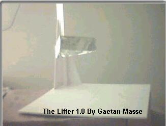
click on the picture to see Lifter1 videos from Gaetan Masse
|
|||||||||||
Jean Louis ...
Je reprends contact avec toi afin de t'informer que j'ai
repliqué avec succés le lifter 1 le 26/11/2001 à 22h30
Suite a de nombreux echecs liés a de mauvaix choix (fils, lifter
trop lourd,trop d'humiditée etc ...) et aprés corréctions,j'ai
reussi à repliquer ton experience .
Tu trouveras en fichier joint une photo de ce test.
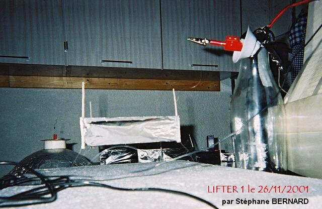
Je vais continuer dans cette voie et tenter de
nouvelles manip.
Je t'enverrais de nouvelles images si je replique avec succés
d'autres manips.
Cordialement
Stéphane BERNARD
Lien vers le site de Stéphane : http://moumra.onzenet.com/moumraV12/evolution/lifter1/lifter1.html
|
|||||||||||
Dear Jean-Louis Naudin,
It took me five lifter frames and two HV power supplies, but
Saturday I successfully flew a lifter. So, chalk up another
successful replication!
I used a standard triangular frame, 150mm on each side, foil
plates 20 mm tall, wire 30 mm above the plates. My power was
supplied by the flyback line of a 14" PC monitor, sacrificed
to the cause of Science, and handled with extreme caution!
At present, I have a HI8 videotape, but no photographs; I plan to
do more experiments this weekend, and hopefully after that I can
scan some photos for you to post, along with detailed specs on
the frame and the power supply.
I have some ideas for other capacitor configurations I'll be
sharing soon, too.
Thanks for all your help, Jean-Louis. It was certainly a thrill
to see the little lifter take off and hang there, buzzing and
straining.
More later!
Sincerely,
Frank Tuttle
|
|||||||||||
Cher Monsieur Naudin ,
Franc succès avec un Lifter Type 1 .Bourdonnements et ozone garantis ! Si une des retenues rompt on peut meme assister à des virages très rapides sur l’aile avec retournement .
Très respectueusement ,
Jacques MARIE
St Gervais les Bains ( Haute Savoie ) FRANCE
|
|||||||||||
Yesterday I took apart old computer monitor, 14 inch,
and connected output from flyback to the upper electrode of
lifter - wire, and ground to the lower electrode which is
aluminum foil.
There was thrust and movement paralel to the axis of lifter, in direction from lower to upper electrode, which was positive and lower was negative. The shape of lifter is rectangle, with size 5cm x 10cm. Distance between electrodes is 5cm - 50 millimeters. Then I wrap round the upper wire with regular transparent scotch tape in order to stop leaking of current and ion wind. Indeed, the hissing was much lower, but lifter still did move in the same direction, from lower to the upper electrode, slightly wobbling at the same time, although the upward force was lower then before when testing without scotch tape.
Again, all the above was done by using pulsed high voltage from computer monitor.
Then I decided to double check the results, by applying the high DC voltage from other generator, which can produce up to 50 kV 5 mA clean DC with almost no ripple - 0,03%. Although the voltage and current were higher, no movement at all was observed with lifter whose upped wire was wrapped with scotch tape.
This confirms results from T.T. Brown
experiments, that only high voltage AC is capable of producing
unidirectional thrust in devices like lifter is. The pure DC,
with no ripple will not produce any thrust, except at the begging
when electrodes on lifter are being charged, once they are fully
charged that effect will disappear.
My conclusion is that experiment confirms theory of this process that only high AC voltage will produce thrust in static devices, one of which is lifter.
Vencislav Bujic
New York, 16 nov. 2001
|
|||||||||||
Hello Jean-Louis
I have just completed a
successful replication of the Lifter v3.0.
It works pretty impressive. I have used 30KV DC , and 0.1mm
enameled copper wire for the runner above the aluminium Plates.
I have attached the pictures which you requested.
Regards,
Donovan Martin
|
|||||||||||
Mon cher JLN,
J'ai suivi tes
conseils. J'ai trouvé au fond d'un garage un vieux moniteur
couleur VGA, vieux mais en parfait état, pour en utiliser la
très haute tension et vérifier le bien-fondé de tes dires sur
les expériences Lifter...
J'ai donc déconnecté la THT du tube cathodique, déconnecté
également l'alimentation basse tension de ce même tube (cela
pour tenter plus tard des bilans de consommation).
J'ai ensuite créé une terre à partir du chassis du moniteur,
et équipé la prise THT du tube cathodique de résistances
adéquates ( 2 résistances de 220 Ko/5W en série ) pour éviter
de griller la THT en cas de court-circuits. Terre et THT ont
ensuite été amenés à l'extérieur à travers des ouvertures
pratiquées dans le capotage plastique du moniteur...J'ai pris
soin selon tes conseils de mettre en place un porte-prise
équipé d'un voyant lumineux et de disposer des affichettes sur
le moniteur pour prévenir du danger de la haute tension...
En ce qui concerne le lifter, c'est une copie quasi-conforme de ton Lifter 01..
Les photos jointes te montrent, pour la 1ère, le dispositif en place avant de mettre le courant. .La 2ème photo te montre le lifter en position haute une fois la tension appliquée...
Bravo Jean-Louis, c'est une affaire qui marche !
Je vais donc pouvoir à mon tour tenter de nouvelles configurations pour participer aux efforts de compréhension de tous les amis que tu as rassemblés sur ce projet..Je vais aussi t'envoyer une vidéo sur ces premiers essais...
So long folks P.P. CLAUZON
|
|||||||||||
Today we had the opportunity to do a number of preliminary tests to determine which direction to do proper tests in.
The results are briefly summarized here:
All tests were carried out with the same power supply with applied voltage in the 5 - 40KV range. In all cases the apparatus weighed less that 2g - usually 1.2 - 1.6g.
Thus far the results have been consistent with previous reports of the Biefield - Brown effect
Many further tests and control experiments are now indicated. In particular we will be constructing a filtered power supply so we can introduce AC ripple current directly on top of a clean DC bias potential. -
Today we picked up capacitors to make a 0.025uF 50KV single capacitor and other HV parts required to construct a 50KV isolated ferrite transformer. We hope to do further tests this weekend.
Dr Mark Snoswell. ( Adelaide 5153, Australia )
|
|||||||||||
Jean-Louis
I have successfully replicated the Lifter v3.0. I will soon be
setting up a website with my results.
The construction replicates your design. I have used 30KV DC.
I seem to obtain very good results using enameled 0.100mm
wire(30AWG).
Just as a test I glued a circular 100mm diameter x 40mm thick
sponge to the base and it lifted it quite easily.
Regards
Donovan Martin
|
|||||||||||
Just thought I'd let you know that I have a basic 200mm a side, triangular lifter working - uses insulated (one side) metal film with addition of ground wire on lower edge as well. Weighs in at 1.5g and lifts very well. Very little corona leakage. No obvious increase in power consumption with the lifter connected to power supply - extremely hard to calculate actual lifter power consumption although it would appear to be very low.
When I can borrow a digital camera I will take some pictures. I have just a bit more work to finish setting up the faraday cage for tests.
If faraday cage tests eliminate static interactions with the environment as driving mechanism then I plan power supply tests...50KV capacitor to smooth out power supply ripple (currently running two transistor push pull circuit, driving TV flyback and tippler, powered by lab power supply) and 50KV insulated ferrite transformer to introduce AC on top of DC bias. I prefer this to a pulsed power supply as more controlled way to investigate power supply .
I also have a fully insulated circular model ready to test - heavier at about 1.7g but with 5KV insulation all around. Initial tests indicate a minimum of 7 - 10 mm plate separation is possible before breakdown occurs (at ~30KV). With the materials I have I will also construct a flat plate with overhead positive wire - this should still be well under 2g total weight and could lift with current power supply.
Time I don't have much of to spare. I will post again when I have something significant to report.
Dr Mark Snoswell. ( Adelaide 5153, Australia )
|
|||||||||||
Hi Jean-Louis,
I finally put up a page on my site that has a little info about the lifters I've built so far.
Please visit :: http://www.gotthatonline.com/advanced_future_flight/lifters.htm
My mother and father came down to my place on the weekend. (they live about 100km from me) And I said to my dad, "do you remember the stuff I used to talk about since I was about 13-15 (1978-1980 when ever Stan Deyo published Cosmic Conspiracy) He said yes. I said "well, have a look at this, and I showed him my lifter v.2. He was amazed at the thing, and like us could see so many possibilities.
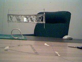
This is a dream come true for me to finally be working towards something good for mankind Jean-Louis.
One day I would like to (I will) "fly" over to France and say "G'day" to you :-)
sincerely Rob Mcleod
|
|||||||||||
Hi all!
I have built the lifter 1 and it worked really good. For powering I used two car ignition coils, powered by the same transistor TIP 3005, using a car- battery. The output of the coils is connected (over two diodes) with a self-wrapped capacitor (4,5nF). Last day I wanted to show it to friends, but it didn’t work very well.
A few minutes ago I tried it again, but it didn’t lift. But then I connected the ground and – lift off! It worked. But only after I connected the minus to the ground!!
Maybe that could help you starting the lifter1.
Bye,
Michael.
P.S.: Sorry, but I have no web cam to take photos of it.
|
|||||||||||
Hi All,
My name Pierre and I am new to the JLN group.
I follow the work that you publish very closely and I must
confess I was very sceptical when I first start learning about
the Lifter experiments. So I decided to slap a lifter together
and test it for myself.
I had an old EGA PC monitor and thought I will use that as my HV
power supply (Excuse my ignorance but I have very limited
electronic experience). I did not have any balsa wood so I used
some stiff cardboard and fabricated the lifter frame from that. I
striped some multi strand twin flex electrical cable and used one
of the single strands of wire as the positive terminal for the
Lifter and normal general purpose aluminium foil as per the
Lifter 1 design posted at JLN Labs.
( ... )
I went on by applying some household 3in1 oil to the wire and the
foil edge and it made a remarkable difference. I now get quick
lift off and stable hover and much less noise.
I would appreciate it if any one in the group can give me some
ideas how I can improve my power supply by using my existing old
PC monitor.
Kind Regards
Pierre
|
|||||||||||
Reproduction réussie du Lifter1 en version light.
Le lifter est un peu différent, j'ai enveloppé les fines tiges de balsa avec du papier alu pour la partie basse.
|
|||||||||||
Dear Jean Louis and All,
I've successfully completed the Lifter1 replication. I've used a HV power supply designed by myself that worked well for the lifter1, but needs to be perfected, since it produces pulse instead of the sinusoidal waves. The pulses period is around 35 uSecs, and the width is around 6uSecs. (See the attached schematic). I was not able to measure the voltage, but I estimate it to be in excess of 40K, since sometimes sparks were able to jump from de wire to the metallic foil. (really very big sparks). You can see in the schematic, that I've used the mains outlet as power source. This is rather unconventional approach, but worked fine. It produced 170 VDC, rooted to the flyback primary through a 220 ohms 5W resistor. The BU208A run cool all time long, as well as the 220 ohms resistor. The 10K potentiometer is fundamental to adjust the point of operation of the BU-208A.
In spite of the very fast pulses, the lifter1 was able to fly, although a bit instable. I've repeated the simple tests for ion wind, and concluded that it is not the main reason for lift.
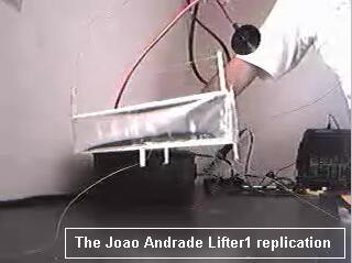 The Joao Andrade's Lifter1 replication (
11-09-01 )
Best regards,
Joao Andrade
|
|||||||||||
Hi fellow levitators!
Just reporting that Josh and I have had a 30kV power unit built
according to the plans of Jean Luis, powered it with a 15VDC 5A
power supply and had excellent fun flying several different
designs of lifter starting with an exact copy of the basic 3
sided "Lifter 1". We are still waiting for arrival of
our 300 k ohms resistors for the positive terminal but just
couldn't wait so we risked the tripler and used it anyway. The
weight of the little craft is absolutely critical, nothing
to spare at all, really fine copper wire for power feeds is
important as well.
We built a four sided craft to the same side dimensions as Lifter
1 and this works best of all so far. We have noticed that if
the top wire is not under tension then it vibrates like crazy
when the craft is flying, enough even to fatigue the thin copper
wire after several minutes and snap the wire altogether. When
this happened on the Lifter 1 type we cut the spare piece of wire
off so there was a top wire only on two sides of the craft. We
were very surprised to see that the performance of the craft was
not really affected at all with the same stable lift as with all
three top wire sections.
( ... )
Cheers
John Leslie
Trimming off the aluminum foil and using sewing thread as an anchor instead of nylon fishing line reduced the weight enough to achieve liftoff. The weight of the device was now 3.6g.
The power supply used was a Gamma High Voltage Research 0 to
+40kVDC power supply, with current limiting from 0 to 1.5mA. The
voltage was increased slowly. Prior to liftoff, the flyer would
behave quite erratically until some minimum voltage was achieved.
Stable lift off was achieved with a 3.6g flyer when the external
voltage applied was +33kVDC at 1.5mA.
|
|||||||||||
Hello all
Today I finally got my lifter to hover around.
I used the basic lifter design from Jean Louis Naudin and a HV
source
(described in the JLN homepage, GPD section) + Voltage Tripler.
( ... )
Regards, Carlos Reis.
|
||||||||||
I used CD as dielectrical disk between two electrodes (flat
and
cylinder). Also the wire can be used instead of the cylinder.
Why is works: Electric field lines inside of the dielectric are
non-linear, so it is Brown's way.
Video of 1999 from my old home lab
http://www.faraday.ru/electrogravity.mpg
Alexander V. Frolov
|
||||||||||
The following Lifters poll is now closed. Here are the
final results:
POLL QUESTION: What causes the Lifter to levitate.
CHOICES AND RESULTS
- Ion wind., 2 votes, 11.76%
- Electrostatic force ., 10 votes, 58.82%
- Anti gravity., 1 votes, 5.88%
- A jump to higher dimension., 0 votes, 0.00%
- Don't know., 4 votes, 23.53%
For more information about this group, please visit
http://groups.yahoo.com/group/Lifters
This device was a successful attempt to create a larger and more stable lifter than my first one. I started out building one according to the directions on Jean-Louis Naudin's website but either my power supply was not strong enough to cause it to lift or the top edge of the foil electrode leaked too much. In either case, I decided to make a smaller one with a lighter frame design.
In this device there are no balsa wood cross members on the bottom of the foils. This is the same way that my lifter 1a was built. Also, the top edge of each foil is wrapped around its cross member and glued back onto itself. This means that there is no sharp foil edge that is on its own, thereby eliminating one source of leakage. To reduce leakage further, the foil is all one piece instead of being made of three individual pieces.
Another enhancement in this design is that the wire height is easily adjustable. At each vertex the wire is hot-glued to a small plastic cylinder. This cylinder, makes a snug fit with the supporting poles but is still easy to slide up and down.
|
|||||||||||
Last night I replicated the experiment and the results are very spectacular.I used version 1 of the lifter and is no doubt about the effect.
I did 2 tests:
1. regarding the change of polarity between wire and
aluminium foil and is a little but observing
diferrence...when (+) is attachet to the wire the
lifting force is biger.
2. ion wind test : by insulating the wire from the
foil with a plastic sheet.The lift is not affected by
this action.
I also agree to the ideea of tring some varied shapes
of the lifter to obtain the best configuration .
Best regards,
Cristian Marinescu
Lifter replications Log Book : Previous Page
Return to the Lifters Builders page