The
Stavros' RF pendulum experiment
An
electromagnetic interaction with the gravity field
Courtesy of
Dimitriou Stavros
By Jean-Louis
Naudin
created on
September 3rd, 2000 - JLN Labs
- Last update September 16th, 2000
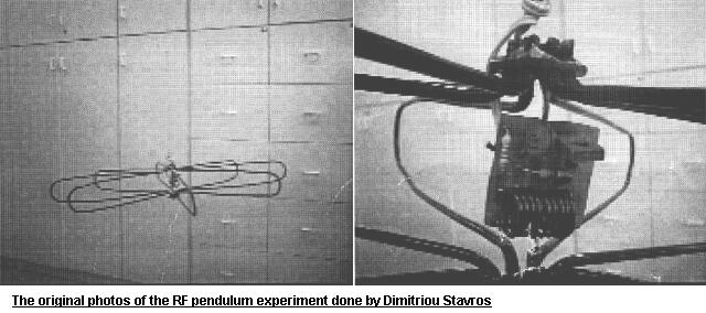
This experiment has been done successfully by Dimitriou Stavros from the TEI-Athens, Dept. of Electrical Engineering in Greece.
" On the pendulum oscillations of a
suspended RF resonant circuit " by Stavros G. Dimitriou
<< Abstract : The
period of the pendulum oscillations of a suspended
electromagnetic resonant circuit formed by quarter-wavelength
transmission line sections is found to be affected by electrical
parameters of the oscillator driving it. Of particular influence
appears to the magntitude of current at resonance, which depends
on the effective quality factor (Q) of the RF tank circuit and
the input driving power. >>
Stavros has said in his
paper that " The
maximum equivalent reduction of g locally is calculated to -1.3% " :
<< Conclusion : A
gravity - interacting field can be generated electromagnetically
and used to reduce the gravity vector locally. Its implementation
uses the horizontal projections of electric currents, intensified
through almost conventional RF techniques. >>
The full Stavros' paper can be found in the Jerry Bayles web site : http://www.electrogravity.com/STAVROS/index.html
Above, the original diagram of the RF oscillator used by Dimitriou Stavros in his experiment
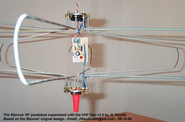
Test RUN #5 ( 09-14-00 ) : I have tried to be closer to the original Stavros' circuit ( above ). My circuit uses a BD827 transistor :
BD 827 specs :
VCB max=60V, VCEmax=60V, VEB=5V, IC max 1A, P.Tot=8WC, hf=40/400
( Ic=150mA) (NPN)
BD 139 specs : VCB max=80V,
VCEmax=80V, VEB=5V, IC max 1A, P.Tot=12WC, hf=40/160 ( Ic=150mA)
(NPN)
2N2219 specs : VCB max=60V,
VCEmax=30V, VEB=5V, IC max 800mA, P.Tot=800MWF, hf=100MN ( Ic=150mA)
(NPN)
The resonance frequency measured is about 83 MHz..
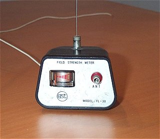
A field stength meter is required
for the tuning of the 1/4 wavelength transmission line at the
resonance frequency.
The P1 potentiometer must be adjusted so
that the power output measured by this meter is maximum.
You may notice, in the upper scope
signal, that when the transmission line is energized by the RF
power,
this generates EMI noise superimposed to the pulse coming from
the opto-coupler.
An interesting wave pattern measured at 1 meter far from the EM tank circuit.
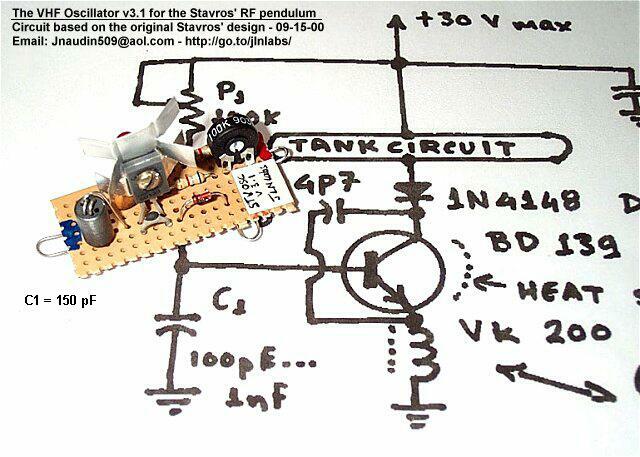
Above, the latest design with a BD139 and a VK200 as mentionned in the original Stavros' diagram
I am very grateful to Dimitriou Stavros for his support and the helpful advices which he has given to me for a successful replication of this experiment.
Reference documents :
On the pendulum oscillations of a suspended RF resonant circuit by Stavros G. Dimitriou
See the New Enhanced RF pendulum design
Go to the Next RF pendulum tests or to the Previous RF pendulum tests
![]() Email : JNaudin509@aol.com
Email : JNaudin509@aol.com
or send
email to the JLN Lab's eGroup at : jlnlabs@egroups.com if you are a team member.
Return to the Field effect propulsion page