The Steorn magnetic
motor replication by JL Naudin created on december 26, 2009 - JLN
Labs - Last update January 5, 2010 Toutes les
informations et schémas sont publiés gratuitement ( freeware )
et sont destinés à un usage personnel et non commercial All informations and
diagrams are published freely (freeware) and are intended for a private use and a non commercial
use.
From the
informations published on the Internet by Steorn, I have decided
to reproduce this magnetic motor and, firstly, to check the
observations and measurements presented in the video of December
15, 2009 by Sean McCarthy in Dublin.
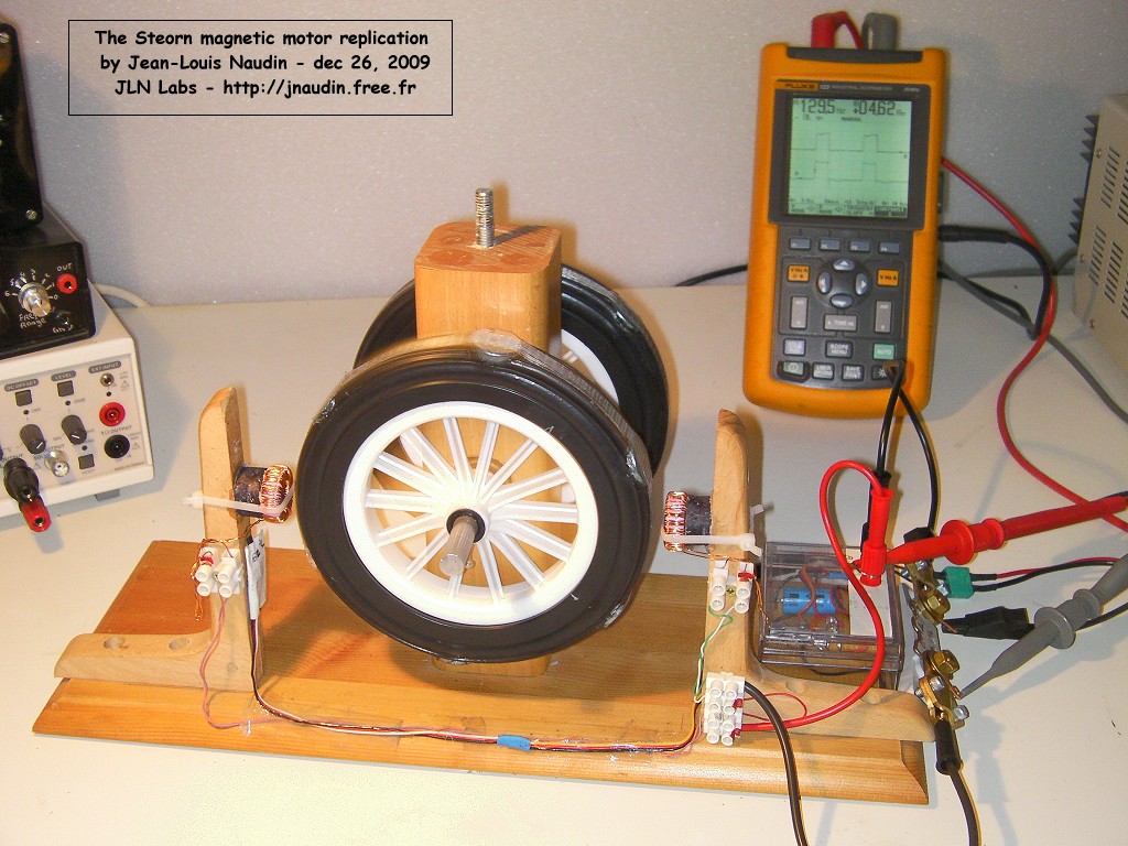
Regarding the
mechanical part, the engine showed by Steorn had its axis of
rotation set vertically. In my case, I have chosen to put the
axis horizontally, only to simplify the construction. The rotor
of the motor consists of 2 wheels, 15 cm diameter, these wheels
are made of a plastic rim and a solid rubber tire. The 2 wheels
are mounted on an aluminum shaft mounted on two ball bearings.
Six holes, 22 mm in diameter and 10 mm deep, were drilled into
the tire to contain 6 magnets NdFeB (Bremag 27) of 27 MGOe (208
kJ/m3). Two toroidal coils with ferrite cores are arranged symmetrically on
either side and with a 5 mm gap from the rotor. The second wheel
behind is not used yet, it will be used later for the generator.
(See photos).
Regarding the
electronics, I have made a control circuit using a Hall effect
sensor Siemens TLE 4905L. This sensor can easily detect the position
of the magnet when its leaves the toroidal coil and thus it
controls the activation of the magnetic field of depolarization.
With this sensor setup, the rotor rotates in counterclockwise
(CCW) direction.
The Hall effect sensor
controls a N-MOSFET power
transistor (BUZ 11) which
is in charge to power the 2 toroidal coils connected in series. I
used 2 ferrite toroidal cores made by Philips (purple color),
reference 4C65-RK190. Outer diameter: 23.6 mm, inner diameter:
13.4 mm, height: 7.6mm. Permeability: 120, specific inductance Al
= 87. Each toroidal core is wound with 67 turns of enameled wire
of 5/10 mm and has an average inductance of 390 µH. The
electronic circuit is powered with a voltage between 9 and 12V.
It can also be powered with batteries Lipo 11.1V (3S1P).
About the
measurements, I have used a digital oscilloscope Fluke 123, the
voltage is measured across the terminals of the coils and the
current through a shunt of 0.01 ohm in series with the output
transistor of the power control circuit.
2 - Tests
results :
The rotation of the engine must be
initialized with a small boost with the hand and counter
clockwise. The increase of the speed is very surprising and the
engine torque is strong. Within minutes the engine speed exceeds
1200 rpm. For security reasons, I added a fiberglass tape around
the rotor to prevent a possible ejection of the magnets. The
magnets are glued with cyanoacrylate glue in their holes.
Here, a short video of the running and the
speed up of the Steorn motor.
CONTROL TESTS:
I recall that the purpose of this experiment
is firstly to check the proper functioning of the Steorn engine
and the facts presented in his video of December 15, 2009 :
A reversal of the polarity of the
coils does not change the direction of rotation,
When the rotor is manually braked,
the supply current in the toroidal coils remains
constant,
There is no ElectroMotive Force
(EMF) and counter electromotive force (Back EMF) induced
in the stator coils when the rotor is turned manually.
Test 1:
Testing the reverse polarity of the coils:
When we reverse the polarity of the supply
voltage, the rotor still turns counter clockwise and the speed
remains identical.
This fact is confirmed experimentally, see
the video below :
Test 2:
Braking the rotor rotation has no influence
on the amplitude of the pulse current measured:
Indeed, when the rotor is braked by hand,
the current amplitude measured remains constant, this fact is
experimentally confirmed.
Test 3 :
There is no counter electromotive force
(Back EMF) induced in the stator coils when the rotor is turned
manually.
The toroidal coils of the stator are
disconnected from the controller and connected directly to the
input of the oscilloscope. When the rotor is being quickly
rotated manually, there is no electromotive force and no counter
electromotive force measured at the output of the coils.
This fact is confirmed experimentally, see
the video below:
3 - To summarize
Today, the Steorn engine reproduced here
confirms the observations and the measurements submitted on
December 15, 2009 by Sean McCarthy in Dublin. This engine, an
atypical configuration, is really very interesting and worth to
be explored and developed because it presents a characteristic of
non-reciprocity of the energy load on the power source through
the breaking of the symmetry (regauging effect). Other
experiments and tests will soon be conducted to better understand
and improve this innovative principle.
Using the potential energy of magnets to
produce a clean and free energy is really worth exploring and
developing very seriously for the future of our planet ...
After many successful tests of the
replication of the Steorn's motor, it is strongly recommended to
increase the number of the turns of the coils to reduce
dramatically the required current for saturation of the
ferromagnetic toroidal cores.
According to my comment above, I have
decided to rebuild the toroidal coils with more turns so as to
reduce dramatically the input current. Click on the picture below
for more infos about the V2.
US 2009/0009157 A1 : SYSTEM AND
METHOD FOR MEASURING ENERGY IN MAGNETIC INTERACTIONS
: An apparatus and method is provided for measuring
magnetic force response time due to the magnetic
viscosity of materials and for measuring total energy
exchanged due to relative motion of magnetic materials.
Voltage and current versus time through an electromagnet
is measured and recorded.... Inventors: Sean David McCarthy,
Alan Simpson, Martin Flood, Maxime Sorin