The Steorn magnetic
motor V2 replication by JL Naudin created on december 26, 2009 - JLN
Labs - Last update January 5, 2010 Toutes les
informations et schémas sont publiés gratuitement ( freeware )
et sont destinés à un usage personnel et non commercial All informations and
diagrams are published freely (freeware) and are intended for a private use and a non commercial
use.
According to my comment about the V1, I have
decided to rebuild the toroidal coils with more turns so as to
reduce dramatically the input current.
The inductance of these new toroidal coils is about 30 time more
than the previous used in the V1. The electronic drivers used is
the same.
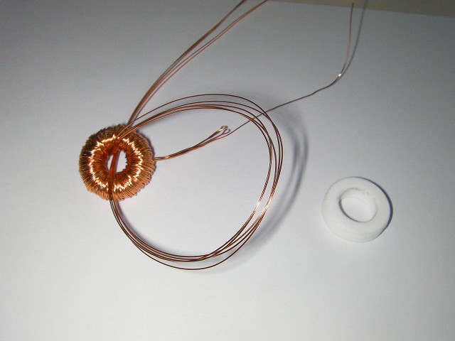
To wind the coil, I have used a very usefull method from Ossie
Callanan (thanks Ossie...). You will find a very well done
tutorial to wind a toroid coil here
The new coils have replaced the old one and the Hall probe have
been placed in a new position.
The position of the hall probe has been optimised with the scope
so as to get the minimum current for the max turn rate.
See a video of the Steorn motor v2 in action
below :
Due to the high inductance (12 mH) of these
new coils, there is a short spike of Back EMF in the measured
voltage produced by the coil itself but NOT induced by the
motion of the rotor. The Back EMF current spike produced by the
inductive coils can't be seen in the current curve because there
is a protection diode in the N-Mosfet transistor (BUZ 11) itself
which protects it and acts as a free wheel diode. This voltage
spike has also been measured when the magnet rotor doesn't move (
see the test : Measuring the current lag ), this confirms that this
Back EMF spike is only generated by the inductive coil itself and
not by the motion of the rotor.
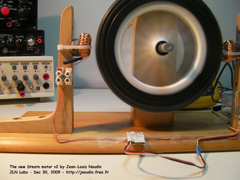
The current (0.4 A) and the voltage ( 12V ) on the main power
supply
6 - No stator coils induction
during a free run at full speed
With these new high inductance (12 mH)
stator coils, I have checked again if there is a measurable
voltage across the toroidal coils when the power supply is
switched off at full speed. In this test the coils have also been
disconnected from the controller during the voltage measurement
with the oscilloscope.
No voltage across the coil has been
measured during this test, see the video below :
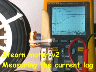
7 - Measuring the current lag in
the stator coils and fine tuning
Now, a
very interesting experiment which shows current lag effect during
the approach of the rotor magnet on the toroidal stator coil.
Click on the picture below to know more.
US 2009/0009157 A1 : SYSTEM AND
METHOD FOR MEASURING ENERGY IN MAGNETIC INTERACTIONS
: An apparatus and method is provided for measuring
magnetic force response time due to the magnetic
viscosity of materials and for measuring total energy
exchanged due to relative motion of magnetic materials.
Voltage and current versus time through an electromagnet
is measured and recorded.... Inventors: Sean David McCarthy,
Alan Simpson, Martin Flood, Maxime Sorin