The
Lifters successful replications
Experimenters
Log Book
created
on October 10th, 2001- JLN Labs
All informations in this page are published free and
are intended for private/educational purposes and not for
commercial applications
Lifter replications Log Book : Previous Page - Next Page
|
|||||||||
| Envoyé via Internet | |||||||||
Hello, Mr Naudin.
I am a brazilian aeronautical engineer and my job is to repair
jet engines for Brazilian Air Force.
I reproduced your lifter1 and it worked well, after same problems
with weight, in 29 october 2002.
I think that the principle of working is modifiyng the
"ether" to produce thrust without other devices to
obtain it.
Some pictures are attached.
Good luck for lifters and your flying saucer!
Major Domingues
|
|||||||||
| Envoyé via Internet | |||||||||
Dear Jean Louis,
Thank you for your most interesting web site and for publicizing
this knowledge!
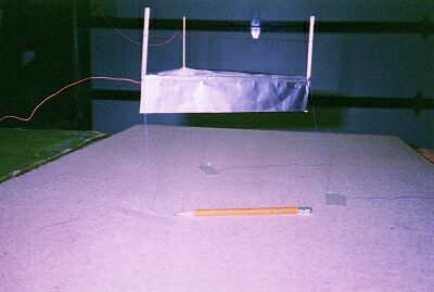
I have had good luck with this lifter which I first flew on
10/27/02. My first attempt was weak and unstable. On this next
one, I used 40-45 gage magnet wire around the top of the posts
(instead of 35 gage), and I took care to bend the top of the foil
around the balsa wood supports (although not all the way around).
I used a shear to give sharp edges on the bottom of the foil and
I'm using a 13" Sharp color TV, model 13N-M100B for my high
voltage source. I don't yet know what the voltage level is but
it seems to be pulsed DC, judging from the way the top wires
vibrate and buzz when not stretched tight.
At first I tried to use the very thin wire for the supply wires
to the lifter but the wires tended to dance around too much and
cause arcing. My inexperience with high voltage caused me to
assume that I could use a 1/4 watt 470K ohm series (protection)
resistor for the positive supply wire. I had some arching
across it's leads, and apparently, this can cause a TV to not
work anymore. :) Now I use 4 carbon resistors in series,
each being 2 watts at 120k ohms. I soldered the negative supply
wire to the foil.
The lifter keeps the strings tight when allowed to elevate to one
foot off the table and seems to have a lot of force. It will
remain steady there for as long as it is powered. If I let it
rise much higher than one foot, it becomes unstable.
I think I need a better way to support the supply wires and to
use a smaller gage with them to decrease the weight while still
preventing them from being pulled to the opposite charged
plates. The stringsshould be lighter also.
Thanks again, Jean and to all who have contributed.
Especially Thomas Townsend Brown.
Sincerely,
Mike Lundberg
Inver Grove Heights (Minnesota USA)
|
Dear Jean-Louis,
I'd like to update my report because, I've found that it is
unsafe to substitute 2 Watt resistors for the 5 watt 470K ohm
resistors that is recommended. On a humid day, my lifter arced
excessively and that blew out my thin coronal wire. This in
turn caused a short when the remaining wire touched the foil and
that caused my 2 watt resistors to become so hot that one
actually came apart. I wouldn't want anyone to think it is to
safe to do as I originally reported.
Thanks,
Mike Lundberg
|
|||||||||
| Envoyé via Internet | |||||||||
Jean-Louis,
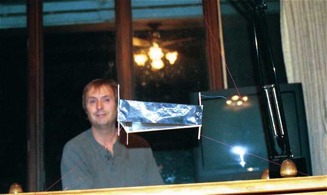
Thank you for the advice. My second v1.0 lifter was a success. I
launched in my kitchen at 12 noon on 10-26-02 and it remained in
stable flight at an altitude of 15 cm for four hours. Then we had
to straighten up to prepare supper. My four-year old daughter was
equally enthralled by the lifter action and repeatedly launched
it about twenty times: "off to the sun!", "to
Jupiter and beyond!", etc. I powered it with an old 14"
HP green-screen monitor (voltage unknown). A photo is attached
for posting.
Oddly enough, on 10-24-02, ABC News broadcast a strange silvery
streak of a craft zipping by a commercial jet. The stop-action
photo looked very much like a lifter. My guess is that someone
has figured out how to put a power source on board and fly it by
remote control: three giant leaps for mankind!
You should get the NOBEL prize in science for hosting this web
site - no kidding! You have done more for "flight" than
the Wright Brothers!
Thanks for all your dedicated work and free exchange of
information.
Bruce French
Tallahassee, Florida, USA
|
|||||||||
| Envoyé via Internet | |||||||||
Greetings Jean-Louis!
Well, here we have yet another successful Lifter replication.
This time it occurred in Seattle WA, at around 1:15am on
10-23-02. The skeptics were in attendance, taking bets on whether
it would just sit, fry or fly. The winner was of course, the
lifter itself, taking off gracefully on the very first attempt.
Jaws dropped, but I just smiled…
Specs on this Standard Ver 1 Lifter are:
Basic 200mm per side balsa triangle (2mm strips)
22-gauge enamel coated magnet wire (stripped on the underside)
35 mm tin foil skirt, gently rolled over the top (total of 50mm)
Power Supply – GRA40 30KV unit purchased from Information
Unlimited (and worth every penny!)
Launch Pad and Support Gantry – press board with white laminate
(great for masking tape) and wooden dowel supports for heavy 10
gauge wire
total weight of lifter 7.5 grams
wire height set to 30mm
Perhaps of some interest is with this combination, I am able to
break down able and load everything into my car, then quickly
assemble the whole production for those on the spot
demonstrations, anywhere at anytime. Now have my own AntiGravity
Road Show, what Fun!
Have a few other, larger designs currently in the works, and
looking forward to sharing updates of these new Lifters when
available. No words can even begin to express my most sincere and
humble thanks to you for bringing this amazing technology into
public view. If even I can pull this off, then anyone can.
Keep up the good work, and best of luck racing to the 100 gram
payload!
Sincere Regards,
Richard Haider
|
|||||||||
| Envoyé via Internet | |||||||||
Dear Jean Louis Naudin ,
Thank you so much for sharing your work with us.
I really admire the work you are doing and I encourage all lifter
builders to continue this work which I believe has a briliant
future.
I am an electronic engineer student from Colombia- South America.
About one month ago I was looking for an electro-magnetism
science project on internet when I was brought to your page.
As soon as I saw the lifters I knew that this was the project I
was looking for, I have always been amazed by levitation so I
read all your page and watched all your videos (...now... I
switch on the power supply...) and all the information I could
about the lifters and after that I followed the plans for the
lifter1.
It took me 4 days of continuous work (only two hours of sleep
between days) to get my first lifter to work moderately stable.
Since then, I have continued to experiment with this amazing
device and I have now built more than 25 lifters.
I have spent so much time building and testing that I had not
taken the time to publish them on your page. Many of them have
been damaged, but today I just finished one that surpasses all
previous ones by far, so I tought it would be a good time to
share my work with all the lifter enthusiast.
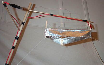
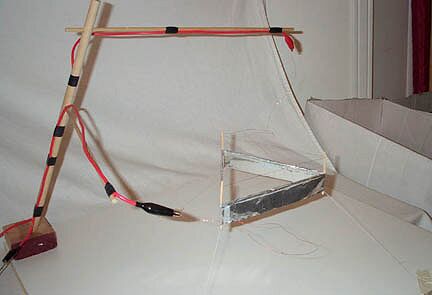
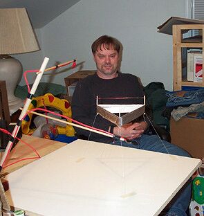
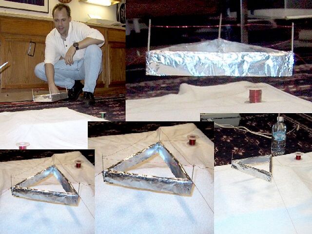
I named it B-2 Stealth Lifter (made it thinking in the B-2 bomber
plane). It took me 10 hours to build it and lots of patience.
When I was about to finish, it was too heavy (compared to my
previous ones) that I tought it was not going to fly, but to my
surprise, when I turned on the power it flew so fast that it lost
one of the theters and crashed into a furniture next to it. I
couldnt believe how good it was working. I set it again and it
flew very stable at about 1 meter high ! (sure it goes higher,
but the landing was so hard I was afraid it would get damaged,
plus didn't want it to fly into my face) . It flies very quiet
and you can feel it has lots of thrust.
I am attaching some pictures, a video, and some info. I will
borrow a megapixel digital camera to send you some better
pictures (mine is 640x480). If any one wants more information I
will be very happy to help.
I have not measured its weight, but it can carry a door key that
I had previously measured at university labs to be 9.23 g + the
key holder metallic ring which weights 2.03g.
I will let you know when I do some more testing with it. I am now
building an oscillator to make the landing and take off more
smooth.
Thank you again and thaks to the people for sharing their ideas
in this page which were very helpful.
To new lifter builders :
If you plan to build your first lifter, this are some advices
which I found very helpful.
1) Get the thinest wire you can, it works better. I got mine from
an old alarm clock. It has a coil in it that works great.
2) Use the thinest balsa wood you can get.
3) Secure the negative wire to the aluminum foil very good. I cut
a little square and I pass the eire through it severeal times in
and out, then I glue this square to the lifter foil. this way the
wire makes better contact. sorry for not including pics right
now, I will do later.
4) Roll the top of the foil and leave the bottom straight.
5) Get a lot of patience!!
Good Luck!!
Juan Camilo Molina E. ( Colombia )
juandmo@epm.net.co
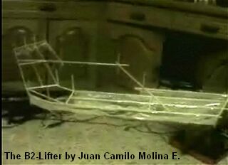
Click
here to see the photos, full diagram and a video about the
B2-Lifter
|
|||||||||
| Envoyé via Internet | |||||||||
Mr. Naudin,
I finally got my lifter to work! I got a 21 inch monitor and built a new lifter and kept it light. I am including 3 pictures of it flying. Could you please put it on your web page.
I would like to thank Kirk Bailey and John Shipley for help with the monitor and power supply!
Sincerely,
Brian Rex Brigham City, Utah
|
|||||||||||
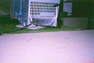
I did mine using only foil, 3 toothpicks, and a piece of
wire. I didn't have any balsa wood. I just added a few tight
folds in the foil to give it some rigidity.
Video at www.MasterComputerGroup.com/ion.avi
By the way, I powered mine with a 14" monitor and learned that a carpet over concrete makes a bad platform - the first test it just arced to the floor, burning holes in my rug. In the photo, it is suspended over a pizza box covered by a towel. The wire from the monitor tube immediately started arcing on the first test to the backside of the picture tube so I had to use heavy wire from the tube to an area outside the monitor before I could connect the thin magnet wire for the corona wire running along the top.
Great site!
Jim Hinsch - Cleveland, OH
|
|||||||||
| Envoyé via Internet | |||||||||
Hi John-Louis!!
HAVE LIFTER....WE'll FLY!!!
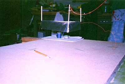
I have finally successfully replicated the lifter 1 on October
10th 2002 Aprox 9:30 PM EST.
A note on this lifter:
I have removed all the enamel coating from the emitter wire
except for the lead to the power supply.
It took a little while to "tune" the lifter, but I got
it at a good point and I also can really "fine tune" it
in the future for what I think will be even better performance.
I have also enclosed a Lighted photo and a corona photo with
ths message.
You won't see much of a corona except for a little around the
posts by the top of the foil.
Daran Francis
SKYHOOK PROPULSION
Pittsburgh Pa. U.S.A.
|
|||||||||
| Envoyé via Internet | |||||||||
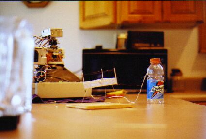
Dear Jean,
I have successfully replicated your experiment of the lifter
capacitor. I first started investigating this technology in July
of 2002. In August I tried making a few versions of the lifter.
The classic trianglular shaped ones are the only ones I could
make fly, the other shapes just tried to move but couldn't get
off the ground.
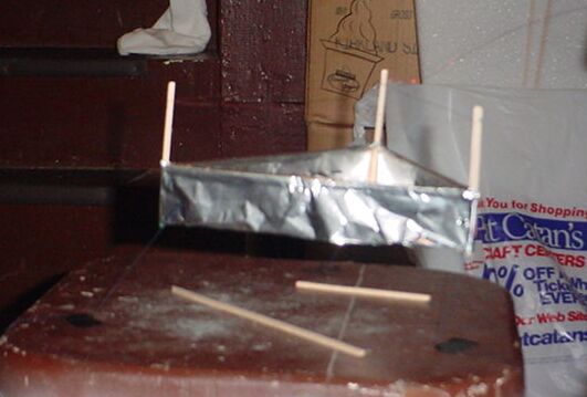
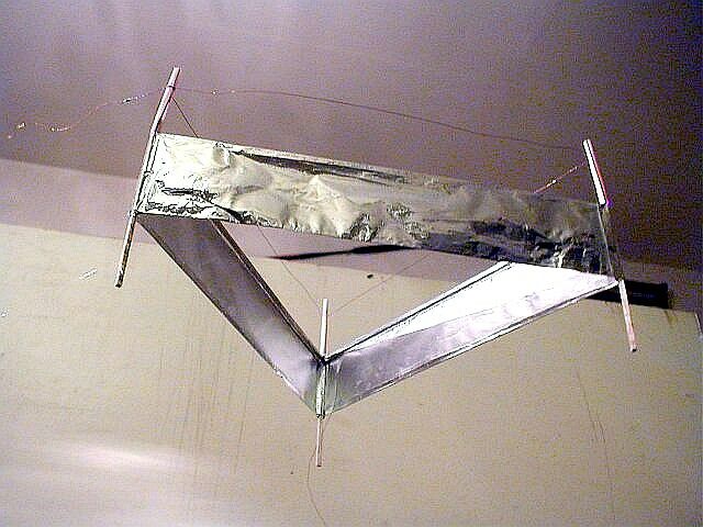
The latest version I have had the best success with is the double
triangle, the triange within the triangle. I just completed some
tests on Oct. 4, 2002. It is about 200mm long per side of the
outer triangle, about 30mm gap from the folded foil edge to the
positive wire.
My power supply is from an inexpensive computer monitor, it only
stays on for about 5 seconds so it isn't the best, but it works.
The tag on the monitor says a 23kv output for the 14" tube.
I have attached some of the pictures documenting my progress.
Thank you for such an informative and interesting site.
Matt Lukes
Independence, KY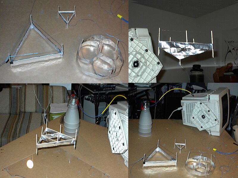
|
|||||||||
| Envoyé via Internet | |||||||||
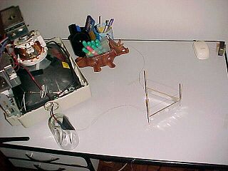
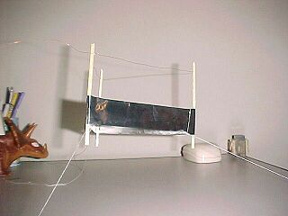
Bonjour,
Eh bien ca y est, j'ai pris hier mon baptême de
l'antigravitation !
Il s'agit d'un modèle pratiquement identique au Lifter 1 décrit
sur le site de Jean-Louis Naudin, soit un triangle équilatéral
de 200 mm de côté et 40 mm de haut en papier alu de type
alimentaire. L'armature est constituée de balsa de 1,5 mm de
section, excepté le triangle inférieur qui a été remplacé
par un fil de nylon légèrement tendu servant à maintenir la
"jupe" d'alu en la rigidifiant.
Les mâts du fil Corona sont de simples pailles à soda, car lors
d'un premier essai des arcs électriques parcouraient le balsa,
peut-être légèrement humide, risquant de le carboniser. Le fil
lui-même a été prélevé dans une cordelière électrique, en
cuivre, il fait 0,1 mm de section et est tendu à 35 mm de la
partie métallique. Le poids total est de 2,4 grammes.
L'alimentation provient d'un vieux moniteur 17 pouces et fournit
25 kv.
Après une première tentative avortée par le
"claquage" d'une des deux résistances de 100 KOhms
montées en série sur l'alimentation, le premier vol a été un
succès complet. Le lifter 1 est monté à une hauteur de 30 cm,
maintenu par trois fils en nylon, faisant entendre un
grésillement caractéristique.
En annexe, une photo et deux captures vidéo des premières
expériences.
Jean Etienne, à Angleur (Belgique).
Avec toutes mes amities,
Jean Etienne
http://www.astrosurf.com/spacenews/sections/perso.html
|
|||||||||
| Envoyé via Internet | |||||||||
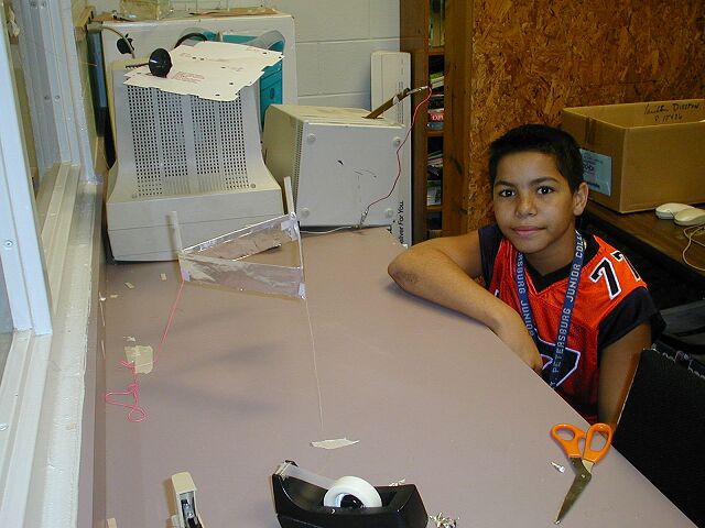
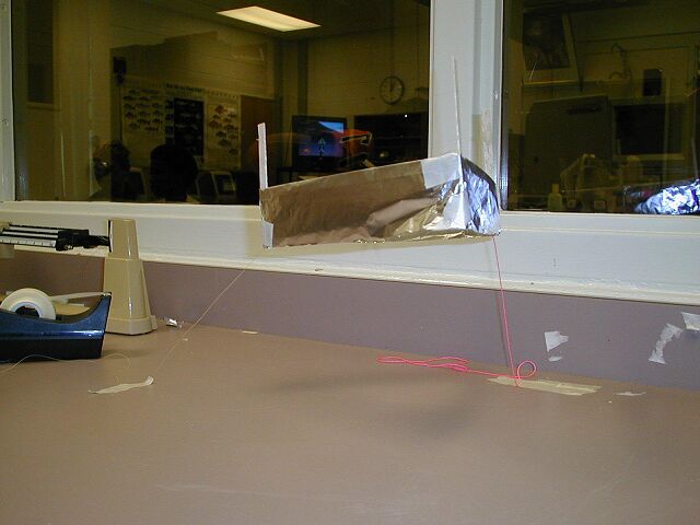
I am a 13 year old student in Mr. Demperio's Physics class. Mr. D believes I am the youngest experimenter to build a lifter 1.
After several attempts I had success with my first lifter
flight on Friday 10/5/02 at 9 am. I used 1mm X 4mm balsa for the
frame and the emitter wire is .002
stainless steel wire at 3.5cm from the foil collector.
My power supply is an old monitor that Mr.D set up for me. I
followed Mr. Demperio's instructions but decided to replace the
foam frame with balsa cut from a large sheet so I wouldn't be
copying the ones he built. I am also working on a square one that
is larger.
Thanks to all, David James Cash
Lifter replications Log Book : Previous Page - Next Page
Return to the Lifters Builders page