The
Lifters successful replications
Experimenters
Log Book
created
on October 10th, 2001- JLN Labs
All informations in this page are published free and
are intended for private/educational purposes and not for
commercial applications
Lifter replications Log Book : Previous Page - Next Page
|
|||||||||
| Envoyé via Internet | |||||||||
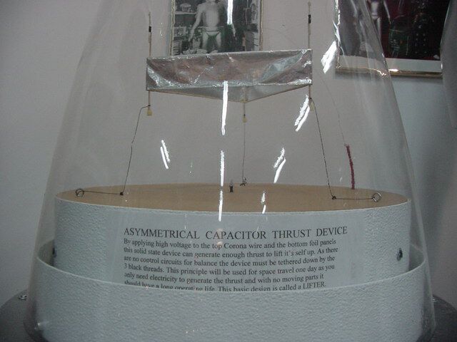
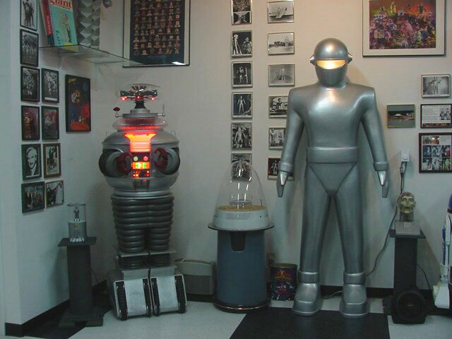
I wanted to build a LIFTER display for the Robot Hut Museum, so it had to be safe and reliable.
I used a 27 inch color TV power supply, this allows me to use
the TV remote control to turn the Lifter ON and OFF. I placed the
lifter in a spare Robby the Robot Dome that I had, this way no
one gets shocked. Now many people can see the Lifter in action in
person!
I have attached pictures of the unit.
Thanks
John R
http://www.robothut.robotnut.com

|
|||||||||
| Envoyé via Internet | |||||||||
Hi Naudin and everybody !!
Oct 6
2002 Takashi Urano (JAPAN)
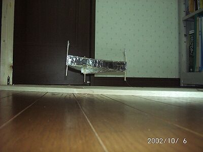
I made a lifter1 (weight:3g) and HIgh voltage generator.
The condition was not good.(humidity: 85%RH).
So I could'nt raise voltage (+27kV).
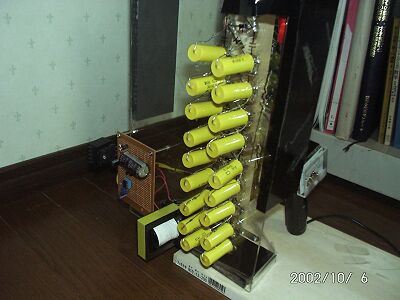
High Voltage generator:
Desighner: T.URANO
Electric parts: I bought diodes,condensors at Akihabara
in Tokyo.
(I live in Chiba city
near Tokyo JAPAN)
Transformer: Material: Ferrite , I wound the wires by
myself.
It works at 20kHz.
I will make another shape "Lifter". and report it
again.
Thank you .
BQX03402@nifty.com
Name: Takashi Urano
Country: JAPAN
|
|||||||||
| Envoyé via Internet | |||||||||
Hi Jean Louis
I have finally got my lifter to fly! (October 4, 2002 at 23h30
local time)
This is my second model. The first model was damaged during take
off attempts when sparks destroyed one of the drinking straws.
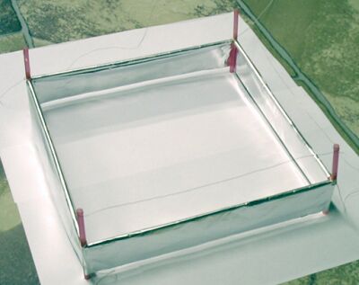
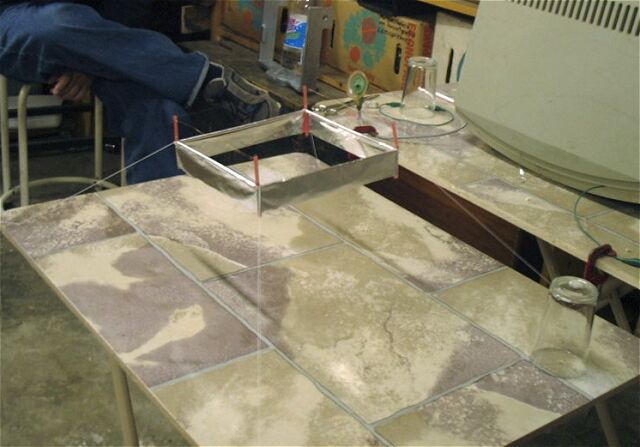
My successful lifter is a 20cm square design built from drinking
staws and four balsa wood connecting pieces at the corners. I
folded the foil over the staws and glued it to the straws with
thinly spread contact adhesive.
The design is quite strong for its weight of about 4.6g. The foil
sides are about 30mm high and the air gab to the wire also about
30mm. The wire is thin copper wire strand pulled from ordinary
twin core flex. For the connecting wires to the power supply, I
used wire from an old relay coil. The power supply is an old
17" monitor giving about 25KV. The positive side of the
pulsed HT DC supply is connected to the foil - it somehow seems
to work better this way round.
I include some photos and a mpg video file.
I want to thank you for this site to distribute information about
this wonderfull new propulsion method. I was motivated to start
building by all the contributers to your site as well as my
coleagues at work especially Hannes van Wyk and Danie Bence.
My location is: San Michele, Noordhoek, Cape Town, South Africa.
latitude
34.2 S, longitude 18.4 E
Regards
Deon Grobbelaar
|
|||||||||||
Hi Jean,
Better late then never...
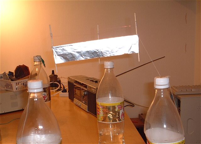
2 weeks ago (18-Sep-02) I've successfully replicated Lifter-1
model. To the best of my knowledge this is the first lifter in
Israel.
I've used the LW-HVPS v1.0 power supply with some modifications:
I used an adjustable power source between 0-30V, this allowed me
to adjust the HV voltage and to have a smooth lift-off and
landing. In order to achieve a high enough voltage I've used a TV
flyback transformer without a built in diode and I connected it
to a voltage multiplier. In order to achieve peak voltage I've
replaced the potentiometer P-1 from 4.7K to 100K. At 30V from the
power source, I measured 20KV at the lifter.
I've placed some photographs of the experiment at http://www.geocities.com/udibr/Lifter.html
All the best, and keep on your excellent work,
Udi Ben-Reuven
|
|||||||||||
I've got my first lifter flying today. Power source mostly
the VS HV PS, except for the big capacitor being 15 uF 370 VAC.
Lifter is triangle shaped, 35 mm very thin Al skirt, 2mm dia
balsa frame, 0.13 mm diam. copper enameled corona wire,
dimensions 280mmx35mm each side, rounded leading edge, corona
distance from Al skirt 60 mm, overall weight 2.5 grams. No pics
by now, but soon. The thing flew on the very first attempt, even
with dimmer on minimum. Some strange noises are coming from
somewhere on the power source, but no heat in any part of it,
neither sparks or problems.
The lifter is not stable, it dances sometimes ad fall down to
the table every now and then, but during certains periods of time
it looks on a healthy strong thrust (sorry, no measurements by
now). I believe instability is caused by dimmer instability,
could anyone give me some advice on this?
After several attempts on different settings for dimmer
(always lifted), I tried reversed polarity (+ to the skirt and -
to corona wire). No lift at all, only noises. Should I discard
all the information saying thrust does not depends on polarity?
Keep sparking!
Eduardo
|
|||||||||
| Envoyé via Internet | |||||||||
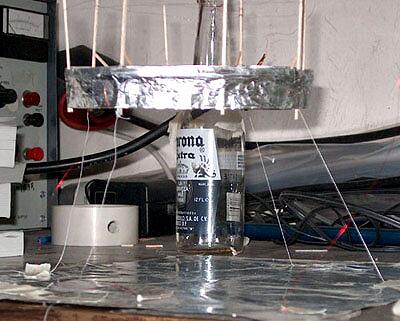
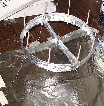
bonjour jean
this is chris gupta :engr/researcher from south florida again.
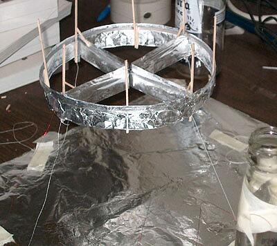
this time i built a perfect round lifter,with four sections.
the balsa wood is soaked in water for 5-6 hours,then taped to a
round pvc pipe and dried overnight. 8" diameter 1-1/2"
(4mm) distance from positive electrode.
using 37 gage nichrome wire. power by 30kv at 5ma, i will post
this on my website with a video by wed sept 25.
next week i am working on the gravity capacitor.
i will kep you informed.
Chris Gupta ( Florida - USA )
|
|||||||||
| Envoyé via Internet | |||||||||
Jean-Louis Naudin,
Bonjour! Today 17-SEP-02, I am pleased to report that I have
successfully replicated the "Lifter 1" experiment! I
will send 7 photos to you over a few messages, 2 are attached
here (I do not as yet have a website for you to add to your
links), they show the various stages of this truly amazing
experience.
Please allow me to describe how this accomplishment unfolded.
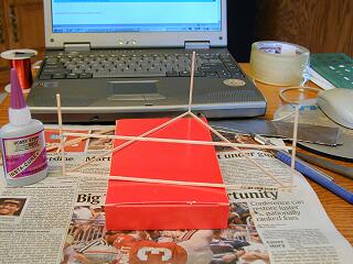
1) [Assembly 3] This just shows the balsa frame under construction, with the use of "purple label" cyano-acrylate glue. I had a spool of 36 AWG enameled magnet wire already on hand, as seen on the left. Regular Reynolds Wrap aluminum foil was chosen (not the Heavy Duty type). The balsa dim's are approx. 1.5 mm x 2.0 mm, standard stock from the hobby shop.
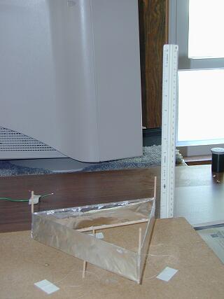
2) [Ready for flight 2] The replicated "Lifter 1" is on the pad, ready for maiden flight! Notice that she is tethered with 3 ordinary cotton threads. Regarding the foil, the plastic-filmed shiny side is on the inner of the side panels. Has your experimentation shown that to be a factor? (Note: the monitor in the background is not part of the experiment.)
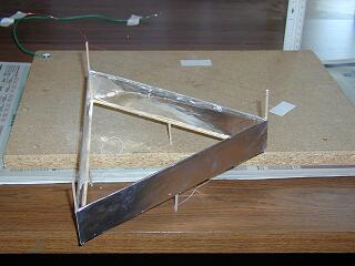
3) [First flight] I threw the switch at approx. 13:08 Eastern US time, and here is the end result with power removed. It jumped forward off the pad, without ever going to steady upward flight. That was OK, as that jump had me convinced!
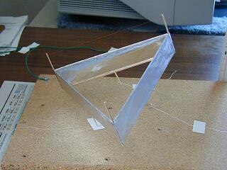
4) [In-flight 1] This is the first photo of the device under power as you can see by the taut thread tethers. It didn't seem to like the positioning of the B+ feed wire, so I made an adjustment to the support of that feed wire.
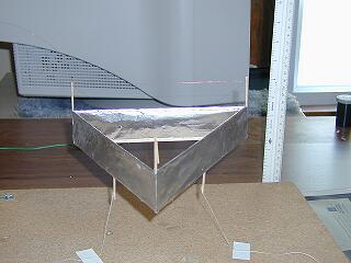
5) [Level flight 2-2] Here I have finally achieved level flight! The corona wire is at ~30 mm gap. You can see that she has risen about 3 inches. Sometimes the noise is a quiet hiss, but usually it is a really raspy hiss, with an occassional arc. Smoothing out of the rounded-over foil edges on top helped eliminate the arcs. Whenever there is an arc, the physical effect is about the same as stalling a wing, as that side instantly drops. The B- wire is soldered to the left lower rear corner. This is quite an ozone generator, as I am sure everyone else has noticed in their respective experiments.
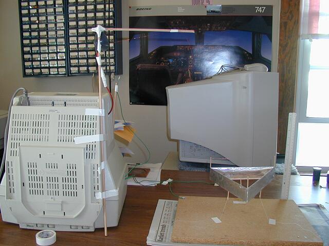
6) [Revision 2 setup 1] Here is the setup with which I achieved level flight. The power source, as you have probably guessed, is from the upside-down monitor, Packard Bell 14" model PB8548SVGL. I do not know the value of the HV output. Perhaps someone else in the group would know. The HV "gantry" supports both the HV output cable and the B+ feed wire. Wrapped in white electrical tape below the suction cup are 3 1 Mohm 2 W resistors in parallel for overload protection. The monitor in the rear, my nice 21", is rotated away from the experiment to prevent inadvertent contact with its CRT.
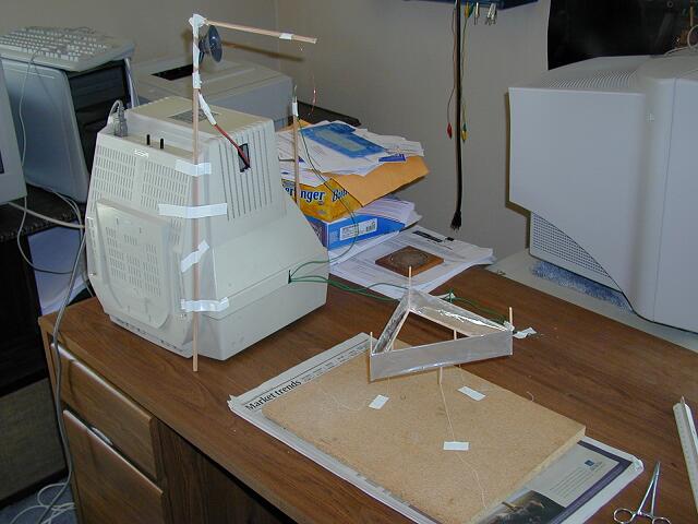
7) [Revision 3 setup 1] I modified the setup slightly in that I removed the wire from the pad board. This view better illustrates the storage of the discharge probe. The monitor supply seems to have internal discharging circuitry, but I use the probe anyway as a precaution. The AC power cord is going down to the floor where I have a suppressor power strip. I operate the strip's power switch with my foot.
That is all for now from Toledo, OH USA. I hope to try a
larger model soon, and to report my observations to you again.
Au revoir et bonne chance!
Brad Gilliam
Toledo, OH
USA
|
|||||||||
| Envoyé via Internet | |||||||||
Hi Jean,
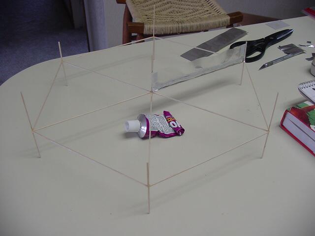
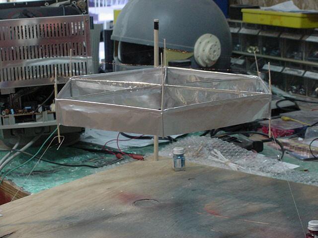
Well I just finnished a 6 section lifter and have attached 2
pictures and a 20 second video. Here is what I learned from this
6 section project.
When I first tested the Lifter with 30 guage wire on the top rail
I was not able to get the lifter off the ground. I'm still useing
my computer monitor for the power supply. So I replaced the top
wire with the micro wire from the battery clock coil and the
lifter was almost lifting. So I tried runing double wires on the
top rail and I was able to get lots of lift as you will see on
the video. This time I did not use a bottom basla wood frame rail
on the foil so this Lifter makes alot of noise, not the frying
sound of High voltage discharge but more of a rating sound. My
first single stage lifter was very quiet as it had the lower wood
rail on the foil. In the first picture you can see the wood frame
for the 6 stage lifter. The second picture is it lifted!
You can see more of my lifter pictures and a Tesla Coil I built
that can produce a 4 foot discharge at my web site. http://www.robothut.robotnut.com
John R.
Spokane WA.
Click on the
Picture above to see the Real Video ![]()
|
|||||||||
| Envoyé via Internet | |||||||||
Hello Mr. Naudin & the Folks,
I'm Vesa T. Korhonen, a microwave & space engineer from
Helsinki, Finland, and I'm glad to inform you that last week I
built two small lifters.
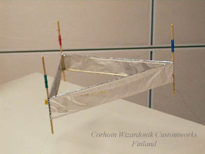
The first one - called The Leijukki - is a basic triangular
one-cell lifter replication (with some details added). The width
is about 28 cm, and the weight - still - unknown. The wire I used
is seemingly some weird 100-micrometer nichrome or tungsten
resistor wire at 170 ohms/meter. Works very well in a lifter, but
can't be soldered with normal means. At least the wire won't melt
with arcing.
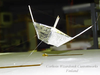
The second one - The Kiulu - is a more experimental one: an
inverted/cut pyramide with four sides. Its dimensions are about
10 x 10 x 7 centimeters, and this one also uses resistor wire for
its electrode wire.
Both lifters are able to lift themselves up the table using only
a simple 17-inch monitor as a power supply, although The Kiulu
(named after a small Finnish bucket used in sauna) seems to be a
'bit' restless in its tethers when lifted up, just like the
buckets usually are if you try to make them fly with electricity.
Fine for experimentation, however. My next, or third, lifter will
be a more sophisticated one and hopefully utilizes a better HV
supply. Let's see how it turns out.
Here are two small pictures of my lifters. More stories and
pictures of them can be found at my Web page: http://www.iki.fi/corhoin
.
Best Regards,
Vesa T. Korhonen
Corhoin Wizardonik Customworks, Finland
Lifter replications Log Book : Previous Page - Next Page
Return to the Lifters Builders page