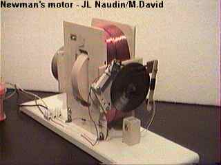
The Newman's Energy Machine
EXPERIMENTERS' FEED-BACK
created on 07/07/98 - JLN Labs - last update on 11/17/98
| Suj : | Re: Newman:preliminary my mot/gen |
| Date: | 07/07/1998 06:36:19 |
| From: | gmeast@pacbell.net (Greg East) |
Hi all,
Over the holiday weekend, anxiety built up to the point that I
finally built a Newman Motor/Generator from the various junk
lying around in my machine shop.
I've had this coil of mag. wire intimidating me for quite a while
now. It's about 29,000 ohms and right around 16 miles long. I
wasn't about to re-wind this into new coils, so I opted for a
Newman design based on his portable...but smaller. If you read
the book, you know its the one with a free-standing coil and the
mag rotor/commutator off to the side.
I've also had a whole lot of Neo's daring me to put them to good
use as well. Here's a description of what I built, how it runs,
what it seems to be doing, and my next steps.
My commutator is about 4-1/2 in in dia. It's flat like JL's but
machined out of double clad circuit board material, .1 thick. It
has 36 pulsing segments...18 for each 1/2 rev/polarity. It's
slip-ringed for direct application of D.C. or rectified A.C.
Also, the machined out insulation spaces between the segments
have been filled so that the
surface of the commutator is smoothe all over.
My Neo's are stacked about 3 inches long and about 1-3/4 square.
They're mounted at one end of a SS shaft...Neo's one end,
Commutator the other, needle bearings in the middle...about 4 in.
separation between
the Neo's and the Comm.
My "burshes" are just wires wrapped around insulated
posts that drag on the commutator surface. Because the commutator
is smoothe, the wires don't jump any as they make and break with
the segments.
At present, I am powering the thing with rectified 'wall power'.
When running, It draws about 3/4 milliamp...that's right, less
than a miliamp and turns at about 90 RPM. Timing is set at around
30 (thirty) degrees advanced.
If you read the book you recall that you can place a neon tube in
parallel across the coil and light it up. Well you be you can. I
put an 8 (eight) foot neon across my coil and it almost stays
ignited continuously. It's not as bright as fully lit, but it's
impressive nontheless. In addition, with the neon lit, the
current dropped to 1/2
(one half) milliamp!!!! and the thing sped up
perceptibly!!!!.....as Newman teaches.
On the scope: Negative current? You bet! By inspection, if
integrated, the negative current is likely greater than the
supply current. Next I'm going to go to higher voltage, screw
around with the timing, sophisticate the instrumentation, improve
the brushes and all that good stuff. These things I will do when
I have another block of free time.
Meanwhile, I'll just watch it run while the neon glows.
I did this in less than two days. If I can, so can all of you.
Try it, you'll like it. I must admit, JLN and Stefan Hartman have
been quite the inspiration. Thanks guys.
Happy building,
Greg East
| Suj : | Re: Newman:preliminary my mot/gen |
| Date: | 09/07/1998 04:21:16 |
| From: | gmeast@pacbell.net (Greg East) |
Hi all,
Just an update here. I have taken the next, simplest step and
'upped' the input voltage from 145VDC to 257VDC (NOT doubled).
What do you think happened??. Well even though the 'coupling' in
this style of Newman Mot/Gen is not very good (rotor-coil
coupling), I was amazed to find the rotor RPM doubled, the
Fluorescent is really cracking and the input current only climbed
2 (two) percent. All that higher-speed pulsing seems to be
forcing the coil to stay in the high-slope region of
the induction curve. This is really exciting!!! It's also running
really, really 'cold.
I also changed the timing a little, and it is now running almost
45 degrees advanced!! Don't really know the effect until I switch
to batteries instead of my present full bridge rectifier.
Additionally, I can't wait to go to batteries because I don't
really think all those 'camel humps' are the best input for a DC
machine. At some point there may develop some weird harmonic or
something???
Later,
Greg East
| Suj : | Important Newman machine measurement results ! |
| Date: | 16/11/98 20:41:31 |
| From: | harti@harti.com (Stefan Hartmann) |
Hi All,
I just came back from our Technical university in Berlin, where I
made today new scope measurements on my old Newman
machine setup now in various conditions.
I think we found now the MAIN EFFECT on which the Newman back
current spikes are based on :
It is a corona discharge effect when using big coils and a
mechanical arc gap !!! It only appears, when the arc gap makes a
"hissing" sound !!! These huge negative back current
spikes which flow back into the power source only occur, when we
had a "hissing" sound at the contacts !
Jean Louis Naudin was right, when he stated, that he could
optimize the negative current pulses, when he used a very washed
out aluminium sliding contact commutator, where he had lots of
sparks ! Now I know it really depends on the "spark
flame" and the hissing sound !
When we had a blue flame at the arc gap, there was no hissing
sound ! Then the input current stayed just at a constant DC
amperage level!
If I did further open the arc gap contacts, suddenly the hissing
sound appears and then the negative staircase back current pulses
appear ! They last as long as the "hissing sound" can
last !
That means, the effect must be based on a special corona
discharge effect.
Maybe it is related to the work of Mr. Corea with his
"abnormal glow discharge effect" and the work of the
Russian Chernetski, who also claimed 5 times more output than
input when using special tubes plasma discharges !
I found the effect, when I also tried the coil without the
magnet. It seems the permanent magnet motor rotor effect is only
a "byproduct" of the Newman machine and does not
account much to the duration of these back current pulses !
It works already alone with the coil and just when pulsing DC
voltage across the coil via this "hissing sound spark
gap" !
I guess with the right contacts and the right distance of the
spark gap one can generate already a higher negative output than
input , so that it stays for longer time in "hissing
sound" mode ! Then an input current amperemeter will just
read negative values, which means, power is coming out of the
device !
The trick is now to find the right optimized arc gap. The effect
scales up with the size of the coil and its weight !
This is why Newman got much better results with his first big
units. There the coils were very big and the commutator was still
so crude, that he had a big spark and much "hissing
sound" at the commutator when the current was reversed to
the coil.
I have recorded the negative current spikes and my experiments
today at the university onto digital DV camcorder and will post
later some pics and movies to my Website www.overunity.com .
Stay tuned !
Best regards, Stefan Hartmann.
--
email: harti@harti.com Web
site: http://www.harti.com
| Suj : | Re: Important Newman spark gap distances ! |
| Date: | 17/11/98 00:38:23 |
| From: | harti@harti.com (Stefan Hartmann) |
Hi Dave,
well yes, I will study these effects on upcoming friday, when I
will be again at the university.
I will try to build various spark gaps now to see, what kind of
metal or carbon electrodes arc gaps will produce the best
"hissing sound" sparks and at what setup there will be
the best negative current output.
As the non hissing blue arc crosses a longer distance, it is the
white colored flame hissing sound spark, which just makes the
effect. And the white spark only appears before the blue arc or
after the blue arc.
So it depends on the distance of the electrodes ! I would say:
about 0.1 to 0.3 mm electrode distance: White arc hissing sound,
big back current pulses !
about 0.4 to 1.5 mm electrode distance: Blue arc, NO hiss, NO
back current pulses !
about 1.5 mm electrode distance: blue arc goes into white arc and
disappears, hissing sound, big back current pulses !
Although I have to recheck that again next friday.
That was related to about 620 Volts of DC input voltage into the
16.9 KOhm coil.
Best regards, Stefan Hartmann.
--
email: harti@harti.com Web
site: http://www.harti.com
| Suj : | Re: Important Newman spark gap distances ! |
| Date: | 17/11/98 00:49:15 |
| From: | harti@harti.com (Stefan Hartmann) |
I had about 620 Volts DC supply voltage rectified with a
voltage doubler circuit from the main grid.
I tried various angle setup magnet versus commutator and always
had about 3 to 5 msec lasting negative back current pulses.
When the magnet rotor was halted, the coil drawed about 33 mA DC
and the voltage dropped a bit. (We only had 3 x 10 uF caps as the
supply caps)
When the rotor versus commutator angle was optimal, the whole
circuit drawed only about 4 mA RMS input current and the rotation
of the magnet was about 4 to 5 rev/sec.
Still many back current pulses, but the positive going input
current was still bigger than the area
under the negative back current pulses.
When I just used the coil and the metal electrodes to put the 620
Volts across the coil via this "hand driven" (manualy
adjusted) spark gap, I could get negative readings of my RMS
input current meter
for some half seconds or so ! (but only, when it had the white
flame and the hissing sound appeared !)
>Maybe the "hissing sound" arc may have more metal
electrode ions, so
> even though the arc is longer, the loss (resistance) is
less???
Maybe it is just a plasma effect based on the right ionic
oxidation ??
Maybe it is a chemical process, where the ionic oxidation process
energy of the metall electrodes are converted into electricity ?
Best regards, Stefan Hartmann.
--
email: harti@harti.com Web
site: http://www.harti.com
| Suj : | Re: Important Newman spark gap distances ! |
| Date: | 17/11/98 08:39:15 |
| From: | JNaudin509@aol.com (Jean-Louis Naudin) |
I fully agree with Stefan, I can also confirm this fact, if
there is a white and bright spark the back current vanish. This
is the reason why I ahev been conducted to build my special
commutator design v1.4. All details about this special commutator
are explained in my web site at: http://ourworld.compuserve.com/homepages/jlnaudin/html/NMac0629.htm
> Although I have to recheck that again next friday.
> That was related to about 620 Volts of DC input voltage into
the 16.9 KOhm coil.
Good !!! we have approximately the same setup : I use 623V and a
17k Ohms coil, so we can compare our results... What is your
inductance value ?
Stefan, could you please:
1) Send us some scope pictures about your negative spikes
observed ?, I would like to compare with my previous
measurements..
2) Conduct some rotation speed measurements ?
3) Build my special spikes currents rectifier ( see at: http://ourworld.compuserve.com/homepages/jlnaudin/html/NMac0702.htm
)
and tell me if you notice the asymetrical current flow that I
have measured ? (don't forget to use fast switching diodes ( like
shottky diodes ))
4) Check is the effect with and without the HV capacitor C1 ( a
mica capacitor ) ?
5) Tell us how much time the Newman's machine is able to run
itself after the power-off sequence ? I have been able to get
4mn30....
Thanks again for all your efforts, good luck in your experiment,
Best regards
Jean-Louis Naudin
(11-19-98)
See the first test feedback from Stefan Hartmann :
11-18-98 - Back current flow measurement also confirmed by Stefan Hartmann
If you need more informations or if you have any suggestions send me your Feedback
![]() Email
: JNaudin509@aol.com
Email
: JNaudin509@aol.com
Return to the Newman's Machine Main page