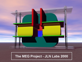
The Motionless Electromagnetic Generator Project
The Motionless
Electromagnetic Generator Project
The
MEG Project
"..This one
works beautifully and produces COP=5.0..." has said Tom
Bearden
Created on 11-18-00 - JLN Labs - Last update 05-10-02
All informations in this page are published free and are intended for private/educational purposes and not for commercial applications The MEG diagrams published in these pages are currently under test by JL Naudin and may be subject to modifications after that they have been published on this site. They are the result of some attempts of a private and fully independant replication by the author. These diagrams are not the original MEG diagrams being tested by the Bearden's teamwork or some accredited labs. Disclaimer: The author assumes no liability for any incidental, consequential or other liability from the use of this information. All risks and damages, incidental or otherwise, arising from the use or misuse of the information contained herein are entirely the responsibility of the user. Although careful precaution has been taken in the preparation of this material, I assume no responsibility for omissions or errors in the diagrams or measurement datas published here. |
US Patent 6,362,718 : Motionless Electromagnetic Generator
( MEG ) An electromagnetic generator without moving parts includes a permanent magnet and a magnetic core including first and second magnetic paths. A first input coil and a first output coil extend around portions of the first magnetic path, while a second input coil and a second output coil extend around portions of the second magnetic path. The input coils are alternatively pulsed to provide induced current pulses in the output coils. Driving electrical current through each of the input coils reduces a level of flux from the permanent magnet within the magnet path around which the input coil extends. In an alternative embodiment of an electromagnetic generator, the magnetic core includes annular spaced-apart plates, with posts and permanent magnets extending in an alternating fashion between the plates. An output coil extends around each of these posts. Input coils extending around portions of the plates are pulsed to cause the induction of current within the output coils.
|
The TOTAL MEG INPUT at the DC input of the control board
The ACTUATOR COIL INPUT ( Primary coil )
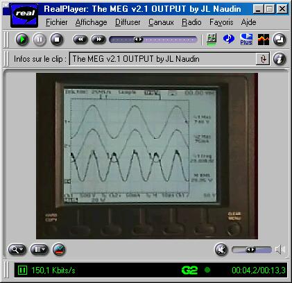
Above : The MEG v2.1 OUTPUT ( Secundary coil )
On the Left :
The Voltage, the Current and the Power
INPUT ( measured at
the DC input of the MEG control board )
On the Right : The
Voltage, the Current and the Power
OUTPUT
The ACTUATOR COIL INPUT
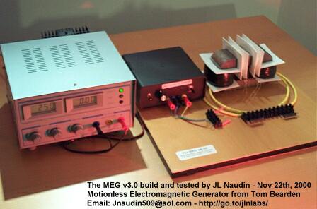
Note from Jean-Louis Naudin : The current has been measured with a 10 ohms ceramic and non inductive resistor ( with a Tektronix THS720P oscilloscope, the probe used is a 1/10 and scope setup for the CH2 is 1000mA/V ), the same resistor and the same method of measurement has been used for input and also the output.
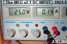
Above :The MEG v2.1 Input at the DC
power supply
See : The MEG v2.1
diagram
Video
of the test done on 11-16-00 ( 228 Kb ), you
need to have ![]()

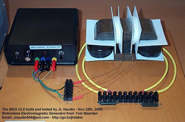
The PowerLite™ C-Cores ( Honeywell ) are manufactured with the METGLAS amorphous alloy.
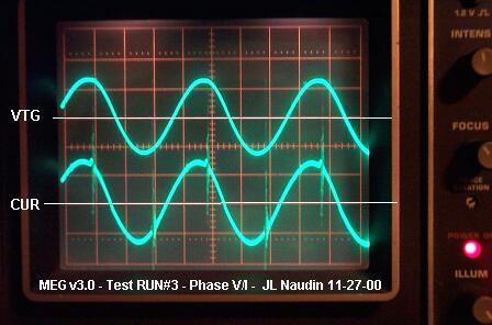
The phase between Voltage and Current
at the MEG Output has also been checked
with an analog oscilloscope ( PM3215 2x50 Mhz Philips ).
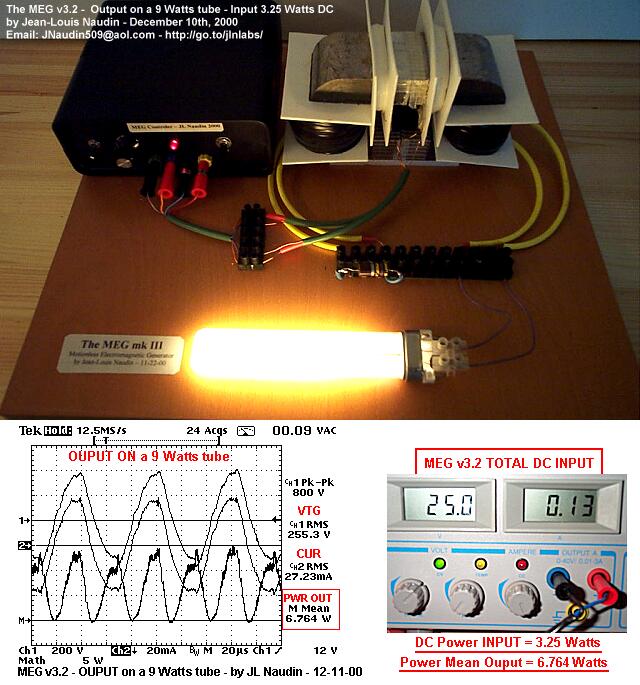
Notes : It is interesting to notice that the measured power required by the MEG electronic control board ( TL494, BUZZ11, LED... ) is 1.75 Watts ( without a load connected at the MEG Outputs ). When the output is loaded with the 9 W lamp, the DC power input is 3.25 Watts. So, the real power used by the lamp is 3.25 - 1.75 = 1.5 Watts at the INPUT with a measured OUTPUT = 6.76 Watts
| MEG Project status ( by JLN
on 12-06-00 ) : You will find below the only facts
about my MEG units that I am able to say today : Not
yet checked : Conclusion
(on 12-06-00) : Now, the BEST verification to do is to convert the "apparent" power measured in useable power such as : light, heat, mechanical energy (in motors).... and also, of course, to close the loop... This has not yet been done today. |
![]() Good advices for the MEG
builders :
The
MEG Notes by Jon Flickinger
Good advices for the MEG
builders :
The
MEG Notes by Jon Flickinger
Technical datasheets :
The TL494,
Pulse-Width-Modulation (Pwm) Control Circuit from Texas
Instrument
The BUZ11
MosFet N-Channel transistor from
Intersil
AMORPHOUS METALS Magnetic Materials
METGLAS®
Magnetic Alloy 2605SA1 (Iron-based) Longitudinal Field
Anneal Typical Core.
http://metglas.com:80/products/page5_1_2_4_1.htm
http://metglas.com:80/products/page5_1_2.htm
http://metglas.com:80/products/page5_1_2_4.htm
See also the :
January 20th, 2001 : Interesting papers and patents :
Interesting papers and documents about the project :
![]() The MEG paper : Extracting Energy
from a Permanent Magnet with Energy-Replenishing from the
Active Vacuum, a PDF document ( 69 pages
1,29 MB), by T.E. Bearden
The MEG paper : Extracting Energy
from a Permanent Magnet with Energy-Replenishing from the
Active Vacuum, a PDF document ( 69 pages
1,29 MB), by T.E. Bearden
Giant Negentropy from the Common Dipole By T. E. Bearden (PDF Format 86 KB)
On Extracting Electromagnetic Energy from the Vacuum By T. E. Bearden (PDF Format 160 KB)
Technical Papers database from Tom Bearden
Some technical infos :
Fe-based
Nanocrystalline Toroidal Core for Current Transformers :
Characteristics: Nanocrystalline
alloy has similar features of high initial permeability and
temperature stability, less gravity and packing factor than that
of Permalloy. Under the same conditions of core size and
performance, it is lighter ( about 1/3 lighter) and cheaper than
that of Permalloy.
Nanocrystalline
Magnetic Core :
Characteristics: High saturation magnetic
induction (1.25T), high permeability, high inductance (ten times
higher than that of ferrite), low loss, small volume, light in
weight, high electric interference resistance, good frequency
performance and high temperature stability.
For more infos about the Nanocrystalline material see :
Magnetic material suppliers :
For more informations, please contact : JNaudin509@aol.com
Return to the MEG project home page