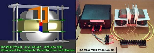
The Motionless Electromagnetic Generator Project
The MEG v1.0 built by JL Naudin
Created on 10-29-00 - JLN Labs
- Last update 11-07-00
All informations in this page are published free and are intended for private/educational purposes and not for commercial applications
![]() See
the lastest results : TEST #5 ( 11-05-00 ) on MEG
v1.0f
See
the lastest results : TEST #5 ( 11-05-00 ) on MEG
v1.0f
![]() See the MEG v2.0 tests
results
See the MEG v2.0 tests
results

The MEG v1.0 build by JL Naudin - October 29th, 2000


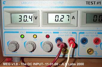
TEST #1 ( 11-01-00 ) :

TEST #2 ( 11-01-00 ) : I have replaced the 555 oscillator by a programmable function generator, for a fine tuning of the clock pulse ( period and duty cycle ). The primary coils are now used in free run mode.


Total Power Input : 3.64 Watts (DC)
JLN's Comments : Now, the MEG circuit v1.0d begins to be interesting comparing to the previous version used in the TEST #1. The total power input measured at the DC power supply is now 3.64 Watts, while the power OUTPUT is 3.37 Watts RMS, this gives an efficiency of 93%... The working frequency is now 1.5KHz Vs the 40KHz used on the original Bearden's MEG. This major difference is due to the use of grain oriented silicon steel material Vs to the Nanocrystalline material used for the core. The latest results are now encouraging, and worth to be explored deeply. May be a COP >1 can be reach with a fine tuning....More to come.
TEST #3 ( 11-02-00 ) on MEG v1.0d


The RMS Power OUTPUT is 3.412 Watts ( clock set at 1.3 KHz, squared pulse, duty cycle: 25% )

Total Power Input : 3.04 Watts (DC)
TEST #4 ( 11-02-00 and 11-04-00 ) on MEG v1.0e
The MEG v1.0e has the same design of the 1.0d version, only the resonant capacitors C5 (100nF) and been changed to C5=100nF+10nF= 110nF, this allow to reduce the working frequency for a better transition of the Weiss domains in the grain-oriented silicon steel core. Now, the working frequency has dropped to 890 Hz. The primary coil #2 (L2) and the secundary coil #2 (L4) have not been used during the tests #3 and #4. This is the best setup ( frequency, duty cycle ) that I have found today.


The RMS Power OUTPUT measured is 5.461 Watts ( clock set at 890 Hz, squared pulse, duty cycle: 25% )


Total Power Input : 3.612 Watts (DC) mesured at the power supply control panel
and 3.339
Watts RMS (DC)
mesured at the input of the MEG controller with the scope

The 5W Load Resistor warm up quickly (44.4°C) during the test.

TEST #5 ( 11-05-00 ) on MEG v1.0e
The new tests on the enhanced MEG control board v1.0f are very encouraging because I have been able to reproduce the exact waves shapes used in the original Bearden's MEG presented in his technical paper : "The Motionless Electromagnetic Generator: Extracting Energy from a Permanent Magnet with Energy-Replenishing from the Active Vacuum," page 67...
See below the scope signal measured at the actuator coil ( Primary ) and also at a loaded output coil (Secundary ).

The Actuator Waves Shapes and the Output Waves signal on the MEG v1.0f
The new MEG control board v1.0f seems now fully in line with the original Bearden's MEG comparing to my previous version... Now, this electronic control board v1.0f must be improved for giving more power output....
![]() See the MEG v2.0 tests
results
See the MEG v2.0 tests
results
![]() Email : JNaudin509@aol.com
Email : JNaudin509@aol.com
or send email to the JLN Lab's eGroup at : jlnlabs@egroups.com if you are a team member.
Return to the MEG project home page