The
Lifters successful replications
Experimenters
Log Book
created
on October 10th, 2001- JLN Labs
All informations in this page are published free and
are intended for private/educational purposes and not for
commercial applications
Lifter replications Log Book : Previous Page - Next Page
|
|||||||||
| Envoyé via Internet | |||||||||
Salut Jean-Louis,
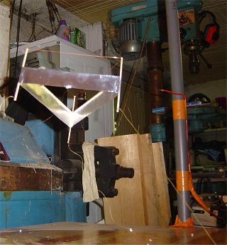
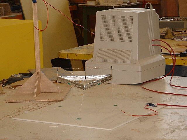
je t'écris pour te faire part de mon tout dernier projet: le
LHD-CC ou le Lifter Haute Densité à Cellules Carrés. La pièce
jointe te montre une idée plus précise de cet appareil. Avec
ceci, j'espère pouvoir obtenir une plus grande poussée qu'avec
un lifter "classique" et ce, à tension et puissance
égale (j'utilise un moniteur d'ordinateur comme source de THT).
S'il s'avère que le LHD-CC produit une grande poussée, il
serait bien d'envisager de faire un empilement pour obtenir une
sorte de "réacteur lifter".
Cela dit, j'ai construit et fait décoller avec succès le lifter
v2.0 et le lifter-cell. A propos de ce dernier, j'envisagerais
d'utiliser 4 lifters pannels pour construire un engin VTOL. En
utilisant comme source d'énergie une pile à combustible et un
transformateur THT.
Bon alors, je te laisse et je te tiens informé du succés (ou de
l'echec) du LHD-CC.
A bientôt.
Cordialement, Damien BOUIC.
|
|||||||||
| Envoyé via Internet | |||||||||
Bonjour Mr Naudin
Cela fait déjà un petit moment que j’ai moi aussi réussie a
faire décoller un Lifter.
Mais jusqu’ici je ne me suis pas déclarer officiellement dans
top 200 !
Et c’est justement par ce qu’il y a aujourd’hui plus de 200
Lifter en vol que finalement je me décide.
Alors voilà !…..
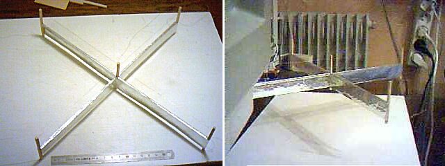
Corona / jupe : 2.5cm
Hauteur jupe : 2.5cm
Hauteur total : 5.5cm
Tension d’alim : inconnu !
Source THT : Moniteur couleur d’ATARI
Section baguette sans vernis: 2.5mm (découper au cutter a partir
d’une
planchette Ep :2.5mm)
La réalisation c’est effectuer par section de jupe de 15cm, en
kit!!
Je me suis décider pour des angles a 90degres pour plusieurs
petite raison.
- a mon avis les angles droit offre une plus grande facilité d’évolution.
- il n’y a plus besoin de gabarit sur papier, facile de faire
du 90degres à
l’œil.
- la section des baguettes en contacte a chaque angle est
sensiblement le même qu’un triangle.
- et donc pour finir la rigidité revient au même.
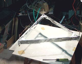
J’ai fait évoluer mon lifter d’une simple croix a un
quadruple carré de 31cm de coté, il décolle avec plus de
vigueur.
Voici ma localisation géographique pour votre carte : France /
Alsace / Strasbourg.
A propos de Carte des décollages !… elle semble être de plus
en plus charger, il serai préférable de remplacer les icônes
de lifter par des points, voir même d’un nombre par pays.
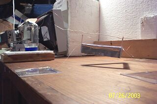
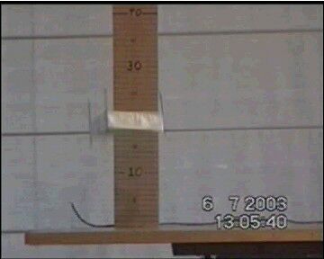
Je joint 2 photos du « prototype 1 » dessus et coté. Ainsi qu’une
vidéo de la taille la plus petite possible, vous remarquerez que
le décollage ne c’est pas effectuer de suite, j’ai souffler
sur le coté du lifter pour casser l’effet de sol !.
Le tout de maigre qualité veuillez excuser ma webcam !
|
|||||||||
| Envoyé via Internet | |||||||||
Hello Jean Louis
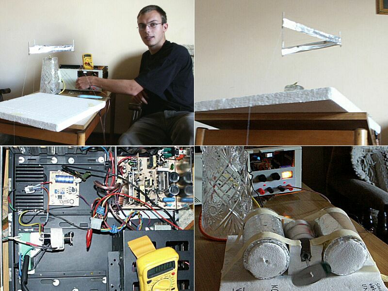
I'm Marek Fertala from Wielun in Poland. Few years ago I
have interested in flying machines in ancient India (called
vimanas). I have read many books, articles and other stuff which
I have found about this topic. Then I have become interested in
the new methods of propulsion, what lead me to electrogravitics
and other ideas connected with that. In this way I have found
Your site, which I found a great mine of information I have been
looking for. Cause I have some technican skills, I have built
some of devices published on Your website. I've built a HV
generator for my electrogravitics experiments (photo included).
That supply is able to give up to 35kV DC / 1 mA (fully tunable
from pure zero) and at a low voltage output from 0.5 to 20 V at
20 Amps.
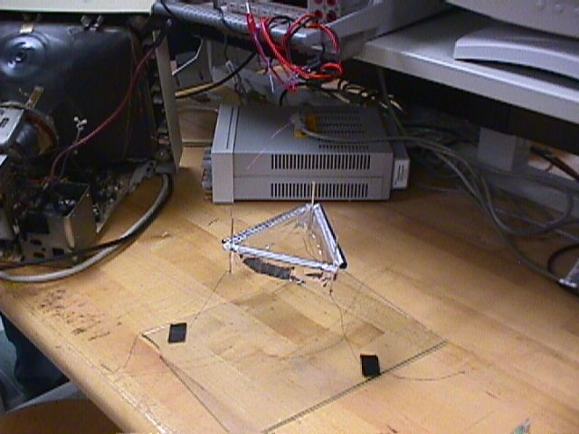
I'm sending You few photos of my latest vimana; generally it is
Your basic-lifter but I'm used to name it vimana :) It is able to
lift off at 8kV only, then takes 3 Watts of power; at higher
voltages its flight is completely stable (I have also enclosed a
short movie of my vimana hovering. It is a *.mov file so Quick
Time player will be needed. I have also attached a picture of
"PFT Motor". It works very good and has amazing low
power consumption >> even works when supplied from
electrostatic machine :)
I'm still searching for new propelling systems, working
beyond present-day physics; lately my interests are going to free
energy. I've got a lot of ideas, but I'm forced to put away most
of them because of the lack of materials, access to a laboratory
equipement etc. Maybe some day I wil have a opportunity to
realize my ideas...
Yours sincerely.... Marek Fertala
Shine on!
|
|||||||||||
Bonjour, j'ai créer avec l'aide d'un ami un Lifter 1. Nous
l'avons fait fonctionner à l'aide d'un THT créer avec une vieux
moniteur. En voici deux photos de mauvaises qualité....
Nous avons également découvert a nos dépend qu'un lifter
monter en 2 minutes avec des pailles de plastique et sans aucune
colle n'étais pas très efficaces ... ni esthétique!
Pier-Luc Beauséjour
Charles Dumouchel
Cowansville, Québec, Canada
|
|||||||||
| Envoyé via Internet | |||||||||
I made the original lifter and it worked!!! I'm in Dallas,
Texas!!
So I made these 2... Please use in the
lifter replication web site!!
I am using a old color monitor for power and the fan is 15"
in diameter...
This actually works as a good fan!! It puts off a bit of wind and
the air seems to be deodorizing at the same time.
My next on will be hooked up to an RPM guage and will be set on
bearings (Roller skate bearings pushed on rod ends.)
One wore of advice of anyone replicating this is pay very close
attention to all wire placment... Spark Gaps are now in more
than one direction.
|
|||||||||
| Envoyé via Internet | |||||||||
Hi! Sorry, I dont' speak these language.
My 30*30cm quadlifter flying on 8,2kV, and can stiring with two wing a little.
JFEry
|
|||||||||||
Bonjour Mr Naudin;
J'ai trouvé votre site très interressant !!!
J'ai construit un lifter 1 en suivant vos plan avec succès !
je vous joins une photo de celui-ci en vol. ( je m'excuse de la
mauvaise qualité de l'image, elle a été prise avec
une web-cam. )
Très respectueusement ,
Sébastien Peloux
|
|||||||||
| Envoyé via Internet | |||||||||
Hello Jean Louis Naudin,
I finaly got my basic lifter running and I'm looking forward to
many new experiments. Please feel free to check my progress at:
http://www.barlowlabs.upgradecolumbus.com/R&D/lifters.html
Good Luck, Best Wishes, and High Voltages to all
Mark D. Barlow
Columbus, Ohio U.S.A.
|
|||||||||
| Envoyé via Internet | |||||||||
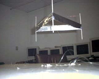
Hello!
Here is a picture of one of our 2-Generation-Lifter, floating
stabile in the air in a laboratory in our university in Emden ( http://www.technik-emden.de/
). Beside our studies, we (three fellow students and myself)
where fumbling around with lifters for quite some time, but last
week we passed the point of no return! We used an old
computer-monitor, which gave us 26 kV. You can see the version of
my friend Till on the pictures, my own was hoovering nearly as
good, if not better (he he). Sadly the batteries where a little
bit weak, therefore we´ve only two pictures. It looks a little
flobby, but it´s flying smooth nontheless. I think we´ve got
the attention of some people here in the university, and
sometimes next week we can use a vacuum chamber for experiments.
I wonder what the microgramm-scale will show. Unfortunately, our
time is very restricted due to exams in two weeks, but we will do
further experiments for sure.
Thanks
(We are: Till Brendemühl, Thole Horstmann, Matthias Busker and
Stephan Kloß [that´s me])
|
|||||||||
| Envoyé via Internet | |||||||||
Bonjour Jean-Louis!
here is my first lifter. first flight on august 21 2003 at
roughly 7:30pm local time (DeKalb, Illinois USA)
its a Triangle 8 inches on each side.
The wire was scavenged from a small DC motor and is .07 mm in
diameter the foil is one inch wide the wire-foil gap is 2.5
inches power was suplied from an old computer monitor...unsure of
exact voltage.
if time permits i will conduct and record the results for some
expiriments on the effects of different dimensions
thanks
Greg Dekeyser
|
|||||||||||
Good morning,
You can add one to the record books from sunny San Diego,
California! I made a single triangular lifter with an equilateral
base of 15.36 cm. I used a Ford Ranger 4 Cylinder ignition coil
attached to a NPN homemade power amplifier powered by a car
battery charger driven by a Goldstar 1 MHZ function generator. An
interesting fact was that my lifter maximized strenth at 16.0KHz.
I don't know if that was because of the natural resination of my
coil or the capacitance of my asymetrical capacitor design of the
lifter but I will conduct furthur research. My goal is to
systematically test 7 independant variables in lifter principle
to maximize lift. They are the following:
lifter design, dielectric constant, applied voltage, frequency,
material, size and temperature. First I am going to build a high
current and high voltage variable power supply, this will take
some work but hopefully it will get us somewhere.
I am currently in the
process of making a very high voltage power supply (around
250-500KV, variable frequency, voltage & current)I am also
compling a list of dielectrics (K > 59.0)and conductors for
use in alloy cathodes and anodes. I've made a website of my
research fully sourced and I should have that up within the next
month. I will keep you apprised of any new (most like accidental)
discoveries.
=====
Joel D. Brinton
San Diego

|
|||||||||||
Bonjour!
J'ai le plaisir de vous annoncer un nouveau succes concernant la
replication du lifter V.1 (video #3 ) : http://perso.wanadoo.fr/flight.zone/
Voici une photo du lifter en vol .
C'est amusant , mais dans l' obscurite , je peux observer 3
minuscules points bleutes quand il est en vol .
Ils se situent sur chacun des 3 angles , au commencement de la
jupe en alu.
(Je vais essayer de faire une capture sans flash , mais j ai
parfois des difficultes a obtenir un vol stable
la rigidite du fils de cuivre + et - , n 'est pas etrangere
au probleme.)
Cordiallement ,
Stephane
|
|||||||||
| Envoyé via Internet | |||||||||
John,
After reading an article about lifters in Wired magazine, and visiting your excellent website, I set about building my first lifter. Finally on the third attempt I was able to achieve a stabilized flight on July 24th(the first two models were a bit on the heavy side). The lifter is powered by a 14" color monitor high-voltage power supply. I found plastic soda straws to be an especially useful lightweight structural material for the frame, drawn together with ultra-fine nylon fishing line running through the hollow tubes. I am now testing various lifter shapes and materials to come up with an ideal platform with which to conduct further experiments. I am confident that a suitable dielectric material can be substituted for the air gap at some point to achieve higher lifting forces. Please update your lifter experimenters logbook to include this latest successful lifter replication(photo attached).
Thank you for all your efforts to popularize this emerging technology.
Sincerely, Robert Rose
|
|||||||||||
Dear Jean-Louis
Congradulations on your web site which has a wealth of information. My lifter, a conventional triangle runs on around 40kV from a 60kv transformer supply, half wave rectified with a single diode. It didn't take off with this until a capacitor was added to sustain the voltage through the full cycle. http://members.iinet.net.au/~pterren/Other_HV_stuff.htm.
I have a bit of a hankering to go for the height record of ? 15m. I also wonder if in the future we might be using nanotube electrodes as the source of corona as they are starting to be used as electron emitters in plasma displays where the furry random surface texture has a lot of conductive sharp points.
Peter Terren
Bunbury, Australia
|
|||||||||
| Envoyé via Internet | |||||||||
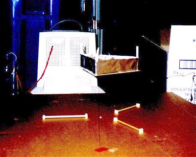
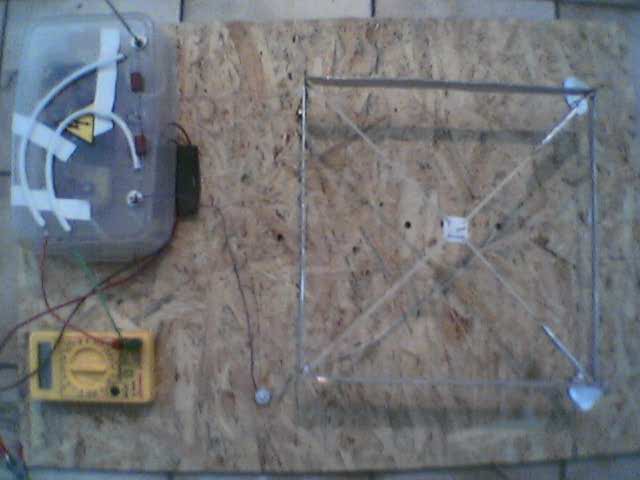
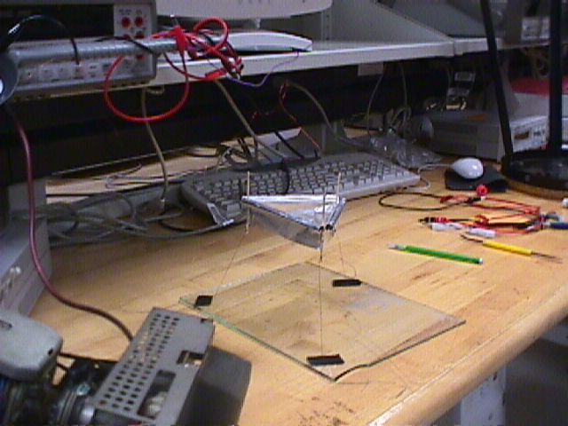
We replicate a Lifter with 150 mm side and about two grams, in balsa wood. We use a HV source capable of delivery up to 35 KV. The current consumption was not mesured due the fact that induced currents interfere in the LCD of the multimeter and tends to damaged it. We are building a new HV source (wich project we enclose, as well as the photo and the movie) that we consider to be very good, with voltage, current and pulse control, but yet quite simple and cheap to built. We prefer to use an automobile ignition coil (super type) and a tripler due to the fact that this kind of transformer are capable to deal with up to 6 amps, instead of flybacks only suitable for 4 amps. The event takes place at 5 of July, and the second (better) movie was done in the day after.
Raul Berenguel,
Invited Researcher at CTEC - Fernando Pessoa University Porto - Portugal
|
|||||||||
| Envoyé via Internet | |||||||||
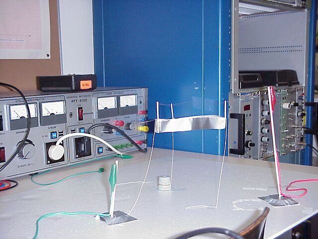
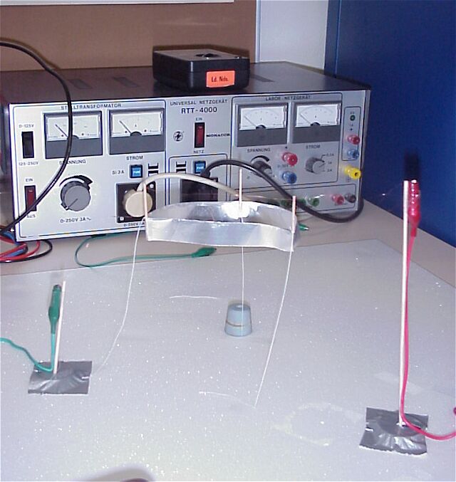
Bonjour,
Mon Père s'est intéressé depuis plus de 6 mois aux systèmes
anti-gravitationnels.
Il a recueilli un maximum d'informations sur la toile et c'est
là qu'il a découvert votre site. A l'époque il m'en parle et
je reste assez sceptique. C'est là que je visite à mon tour
votre site et me surprend à en être fasciné. Le but est donc
alors de reproduire ce qui a été déjà fait par tant d'autres.
Etant électronicien j'ai pu concevoir en m'inspirant de vos
schémas une alimentation THT, sans avoir eu quelques déboire
étant beaucoup plus familiarisé aux courants faibles.
Une fois les difficultés de l'alimentation surmontées, il a
bien fallu réaliser un lifter. J'ai réalisé deux prototypes
triangulaires, mais bon ça voltigeait pas très haut. C'est
alors que j'ai ramené l'alimentation THT chez mon père, là il
a réalisé trois lifters non fonctionnel en règle général à
cause de la masse des lifters trop lourd Mais après cette mise
en jambe il a réalisé quelques petit chefs d’œuvres.
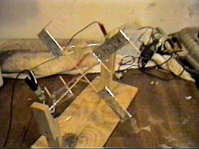
Je vous livre les images des derniers prototypes les plus intéressants.
Une petite chose au passage nous nous sommes aperçu que le bord
supérieur de l'aluminium n'était pas absolument obligatoire, il
faut que l'aluminium soit suffisamment tendu pour ne pas avoir
les cotés qui se mettent à vibrer et obtenir la force opposée
à la gravité.
Comme sur les avions Bi-plan une parties des structures est
remplacées par des tenseurs
(fil de soie).
Il est illusoire de penser qu'à l'heure d'aujourd'hui on pourra
rendre autonome ce genre de système sur terre. Mais je pense que
la barrière n'est pas si lointaine. Ne peut on pas imaginer une
alimentation ayant un volume de 3-5 cm3 une masse de 2 g
fournissant 30 KV et une puissance de 15 Watt pendant une dizaine
de secondes. La pile à combustion me semble une piste
intéressante mais ne doit certainement pas être la seule.
Amicalement VIEIL Thierry et son père VIEIL Aimé

|
|||||||||
| Envoyé via Internet | |||||||||
Monsieur,
Suite à vos conseils et après quelques tentatives plus ou moins fructueuses qui ont d'ailleurs permis d'avancer, une dizaine de lifters ont été construits au sein l'Université de Technologie de Compiègne, (certains lévitant mieux que d'autres!). Les lifters ont, d'ailleurs, provoqué un vif intérêt aussi bien des étudiants, des enseignants chercheurs que du personnel. Je vous fais part d'ailleurs de quelques photos ( en plusieurs envois). Ce projet nous a d'ailleurs donné l'idée de poursuivre et de créer une association et pourquoi pas un challenge inter-université. Les différents prototypes seront présentés au cours de la fête de la science qui se déroulera du 17 au 19 octobre 2003 à Compiègne et nous serions très honorés si vous pourriez venir pour y faire une démonstration ou toute autre forme de présentation sur votre passion le samedi 18 ou Dimanche 19 octobre.
Je reste à votre disposition pour d'éventuels
compléments, très cordialement, Christelle Kowandy.
*****************************************************************
Christelle Kowandy
Génie Mécanique - Laboratoire Roberval
Compiègne
|
|||||||||||
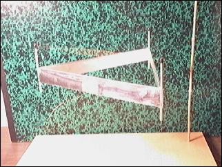
Bonjour Jean Louis Naudin,
j'ai envoyé sur ton site une série de petites vidéos ainsi que
des photographies,
Je serai honoré que ces documents puissent ètre diffusés sur
le site;
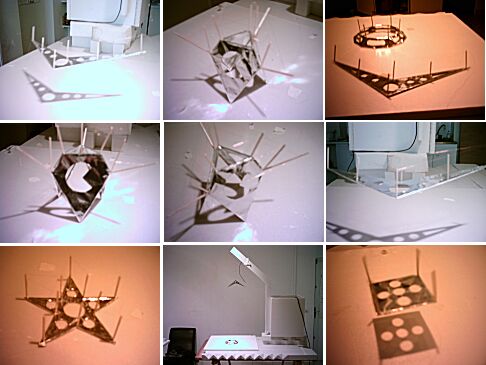
Comme tu as pu le remarquer, la structure des liftres est
differente du
modèle standard.
En effet la jupe en aluminium se situe sur un plan horizontal et
diagonal.
Les formes sont quand à elles diversifiées.
Salutations,
cosmin.
Lifter replications Log Book : Previous Page - Next Page
Return to the Lifters Builders page