
The
Lifters successful replications
Experimenters
Log Book
created
on October 10th, 2001- JLN Labs
All informations in this page are published free and
are intended for private/educational purposes and not for
commercial applications
Lifter replications Log Book : Previous Page - Next Page
|
|||||||||
| Envoyé via Internet | |||||||||
Hello,JNaudin.
I achieved the flight of lifter that had 4 section. I'll send this picture and movie.
Good bye.
Yusuke Kudo from Japan
|
|||||||||||
Hello.
I am Daisuke Nakao, In Japan, 5m of Lifter was floated 15m.
Thank you for your consideration.
Daisuke Nakao

Click
here to see more photos about this experiment
|
|||||||||||
Hello Fellow Lifter Groupies!
I must first offer my sincere congratulations to both Jean-Louis
and his tiny friend Orville for successfully completing their
first living electronaut experiment. Most Excellent! Just another
grand electrogravitic milestone (kilometerstone I guess in
France) for the rest of us to catch up with, if we can.
Recently flew for the first time my own much more humble
experiment, which I refer to as the Hex-Lifter (for images and
web cam video,
check out my own budding lifter page found at http://www.serv.net/~only1egg/science/LifterPage.htm
) The overt reason behind this six-sided design is that personal
experiments showed most of the leakage (arcing) occurred at the
corners. This method of construction has twice as many corners,
and with wider
angles than the standard lifter, thus allowing the
electrogravitic field to spread itself around the cells somewhat
more evenly. Or, that's the theory anyway… All the same, while
I don't have much to contribute to the technical exchanges
presented by some Lifter Group members, having build a few
successful lifters now, I would like to offer a few more
pragmatic observations to experimental newbies…
First of all, it can not be stressed enough that when building
lifters… Build Them As Light As Possible! This is of course a
skill that comes with practice, so by all means, construct a few
lifters to develop the proper technique. You will find it rather
amazing just how tough a balsa structure can be when correctly
tensioned with tin foil and wire. My own construction technique
includes a lapping joint between lengths of balsa, providing that
extra bit of surface area to
hold them together. (not to mention that the little dab of glue
is possibly the strongest part of the structure) I also use
very tiny pieces of balsa glued in place to reinforce these
joints and corners, which seems to add very little weight, but
increases strength tremendously. (watch out for those sticky
fingers…) Another suggestion is to round off the tops of the
side lengths of balsa, which I do by careful sanding prior to
final assembly. This way, when you wrap the tin foil over the
rail, it can be pulled down more tightly, thus avoiding more of
those sharp, crinkled edges where the worst arcing can occur.
(which is very bad for your power supply, by the way!)
Next, use the finest gauge of wire that you can get your hands
on, as it makes a noticeable difference in emitter wire
efficiency. If possible, splurge on a spool of Information
Unlimited's ultra fine Stainless Steel Wire, which although
sometimes challenging to work with during construction, really
works quite well in flight. I also found that if you take regular
clear tape, and roll it tightly with the sticky side out, it can
be used on the uprights to wrap the wire around. Not only does it
help hold the wire in place, but it makes it much easier to slide
the emitter wire up and down for any necessary fine tuning
between flights.
Finally, by all means do experiment virtually before actually
constructing your lifter. It was most helpful to refer repeatedly
to the Lifter Solver Calculator found at
http://jnaudin.free.fr/lifters/calc/thrust.htm
. The primary reason for doing this is to accurately work within
the Voltage/Amp conceptual box you have available, which
seemingly is the only real limit to building those very larger
lifters. Looking over the various designs coming forth from other
experimenters, it appears that almost any configuration can be
made to fly IF you remember to work within these Voltage/Amp
limits.
Well, that's it for the moment, I hope these suggestions are of
some use to those just starting out building their own lifters.
Best of luck to everyone, let's keep those lifters flying, and
remember to play safely with your high voltage power source. (I
for one have a far more healthy respect for electricity, after
mistakenly sticking my finger where it did not belong! OUCH!!)
Just Another Happy Lifter Maniac,
Richard Haider
Seattle WA

|
|||||||||||
Bjr,
vous trouverez sur mon site quelques photos de mes
expérimentations avec le lifter héxagonal de C.Dupré.

Salutations
D.Nardi
http://d.nardi.free.fr/lifter.htm
|
Cher M. Naudin,
Nous sommes un groupe de quatre élèves en terminale
scientifique au lycée international de Strasbourg. Dans le cadre
des TPE (travaux personnels encadrés), et du thème "Espace
et mouvement", nous avons choisi la lévitation comme sujet
pour notre travail, suite à l'article paru dans "Science et
Avenir".
Après plusieurs tentatives, et une construction rigoureuse des
lifters, nous avons réussi l'expérience avec des lifters du
type basic.
Notre THT délivre 23 kV (issue d'une vieille télévision
couleur), nous avons choisi une résistance de protection de
valeur 4,7 KOhms. Quelle expérience impressionnante !
Merci pour votre travail,
Cordialement,
Stéphane HARTER,
Sébastien LUTZ
Andrew O'NEILL
Jean-Philippe ZORN

|
|||||||||||
Cher M.Naudin
Cela fait déjà quelques temps que je ne donne plus de mes
nouvelles et pour cause, mes expériences sur le basic lifter ont
évolué.
Je me présente de nouveau, M. Julien Brette, étudiant en
classes préparatoires scientifiques à Limoges. Je vous avais
contacté il y a deux mois pour diverses questions sur votre
fabuleux projet, à savoir celui du lifter.
A cette époque, mon emploi du temps ne me permettait pas de
réaliser mes expériences, mais les vacances de noël m'ont
permis d'y remédier. De plus, j' étudie maintenant ce projet
avec un camarade ( Cyril Hospital ), ce qui est encore plus
motivant.
Je vous rappelle aussi que l'étude du lifter fait l'objet d'un
TIPE ( Travail d'Intérêt Personnel Encadré ), projet donnant
lieu à une évaluation lors des concours d'admission aux écoles
d'ingénieurs ( qui se dérouleront pour nous à la fin de cette
année scolaire ).
Vous m'aviez demandé de faire un compte-rendu de nos avancées
et voici mes ( ou plutôt nos maintenant) impressions:
_ après deux après-midi, nous avons enfin réalisé une
lévitation du lifteur : en fait, nous avons effectué une
première expérience mais le lifteur ne bougeait presque pas.
C'est pourquoi nous avons changé de résistances ( pensant
qu'elles nous consommaient trop de puissance ) ; nous avons aussi
modifié le lifteur en l'allégeant et nous avons alors observé
un léger saut du lifteur ( source d'encouragement ! ).
_ c'est alors que nous nous apercevons que la THT ne délivrait
que 24 kV. Nous avons donc cherché d'autres écrans. Nous
renouvelons ainsi nos expériences avec un moniteur délivrant
jusqu'à 30 kV. Et là miracle ! , ça marche. Cependant, une
étincelle mit le feu à notre lifteur ; nous avons donc coupé
le courant et en déchargeant le lifteur, nous avons
"grillé" la THT ( pour cause de résistance de 60
k-ohms seulement, et cela faute de mieux )
_ après maintes expériences, les résultats ont été enfin
concluants, que dis-je, impressionnants ( encore mieux que sur
les vidéos ! ).
_ désormais, le lifteur V 2.0 vole également.
Maintenant, place à l'interprétation : nous essayons de
comprendre les phénomènes cause de cette lévitation, sans
prétendre les démontrer, loin de là s'en faut ! Nous aurons
par ailleurs quelques questions à vous soumettre.
En attendant que nous vous envoyons les photos, tous nos
meilleurs vœux pour cette année 2003 en espérant qu’elle
soit propice au lifter et à vos expérimentations.
PS : toutes nos amitiés à Orville !!!
Julien Brette - Limoges ( France )

|
|||||||||||
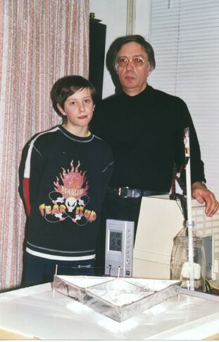
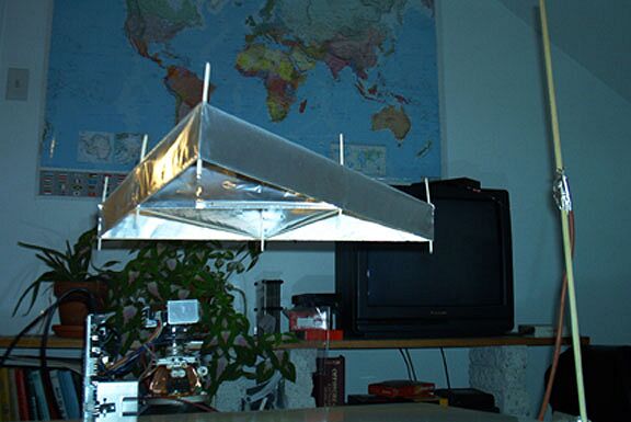
Cher Jean-Louis,
quelques mots pour vous annoncer qu'avec mon fils Vivien
(12ans1/2) nous sommes parvenus à reproduire votre expérience
Lifter 2.
Nous avons eu cependant quelques déboires:
d'abord en utilisant un ancien moniteur noir et blanc : aucun
résultat (quelques frémissements du papier alu)
ensuite avec un moniteur couleur datant de 1990:
manque de puissance occasionnant des instabilités de vol (je
n'ai aucun des caractéristiques de ce matériel)
En réglant les fils d'arrimage en nylon je suis parvenu à le
stabiliser mais à seulement 10 cm au dessus de la table.
Le support d'envol utilisé était constitué d'une plaque de
carton millimétré posé sur une plaque de polystyrène expansé
de 5 cm d'épaisseur.
Amicalement votre
Jean-Pierre TURMEL
Vivien TURMEL
ROUEN FRANCE

|
|||||||||
| Envoyé via Internet | |||||||||
Voici le lifter V2 selon vos plans. J'ai vaporisé un produit pour les chapeaux de distributeur pour prévenir les arcs entre les deux électrodes, ca marche. Quelqu'un a-t-il pu expliquer pourquoi la force résultante est toujours dans le même sens indépendemment de la polarité des électrodes? Ce comportement me semble en contradiction avec l'explication mettant en cause le vent ionique ou électrocinétique.
Merci pour avoir succité en moi la rage de reproduire au plus vite ce phénomène extraordinaire.
A suivre.
Bien à vous,
Michel Dumont Qc. Canada
|
|||||||||
| Envoyé via Internet | |||||||||
Hi!
I am Martin Filipiak, from Szczyrk, Poland. Earlier I built other
device,
(you can see this at: http://www.pibn.topnet.pl and my home
server http://80.49.111.128/ ).
I am amateur constructor and this is my hobby.
So, I built some lifters.
As a power source I used only 2N3055, trafo and voltage
multiplier cascade from color TV.
It produces about 30 kV.
My favourite lifter is "titan". In my opinion, It look
is very futuristic...
I built too for my lifters "aerodrom". I showed this
lifter on the Forum
unconventional contrivance and ideas in Wroclaw (5-6 october).
There I was with my team-PIE.
This lifter doesn't need connect to ground.
This device is fantastic!
technical info:
-triangle lifter
lifter height: 5 cm
aluminium sheet height: 2 cm
total lenght aluminium sheet: 36 cm
-titan:
lifter height: 6cm
aluminium sheet height: 2 1/2 cm
total length aluminium sheet: 58 cm
gap: 3cm
*This lifter was runing 46 hour non-stop.
Photos:
008.jpg it is my third lifter, but first function.
009.jpg other view this lifter.
011.jpg this lifter with him admission.
012.jpg ready to fly?!
013.jpg "titan" it is my favourite lifter!
014.jpg zoom for "titan".
019.jpg I with my lifters
034.jpg and my photo...
I have too many films and photos this lifters...
Martin Filipiak.
<good bye>

|
|||||||||
| Envoyé via Internet | |||||||||
Well it took a little patience but I have learnt a lot . I was
suffering from arcing so the lifters didnt fly for long, the
arcing was especially bad at the point where
the +ve supply joined the lifter, I soon realised that I needed
to keep the +ve supply as near as vertical to the lifter as
posible. This may be due to the fact that I am using 0.08mm
stainless steel wire which is not coated. I also believe that I
am not getting a very high output from the 15" dell monitor,
as I am severely restricted to the weight of the lifter.
I followed Jean Louis's plan for the lifter 3 which has basla
wood at the top and bottom of the foil (I even think the balsa
wood was thinner than he suggested) but still I didnt get any
lift - just a bit of movement. So with my scalpel in hand I
hacked off the bottom balsa wood - and hey presto got instant
lift. As this was a version 3 it was very stable, and the only
problem I have now is the monitor's power supply cuts out after
10-15 seconds, even without any arcing .
I have also made a single cell out of kids plastic straws, this
is quite good as you dont need any glue to make the triangle and
vertical supports for the corona wire. I also found that using
the plastiv straw on the vertical allowed me to slide the corona
wire up and down very easily and was able to use this to test a
variety of heights - which only goes to prove what we all know
that 30 - 35mm seems to be the optimum height for the +ve wire (
at least with this lifter anyway)
Hope some of this helps any one elso just starting out!
Here's to bigger and bigger lifters!!
Alistair Gillan

|
|||||||||
| Envoyé via Internet | |||||||||
Mr. Naudin and other lifters,
I builded a "tiny" lifter consist of a single cell size
8cm, alu 2,5 cm.. wire distance 3 cm (see the log)...
I was playing around with payload ( we go for the 100g of course
:) ) and discovered something strange...
When placed a peace of normal paper on top of the alu foil..
about every centimeter a hilighted spot appears. So it seems that
the electrons are gathering on these spots... (See my attached
movie),
Does this mean that the smallest cell you can make is about 2 cm
for each side ??.. Have you seen this effect before ?....
Regards
Robert de Roode,
and a Merry Christmas and a Happy New year.
(contest for Next year, a floating christmas tree) ;)

|
|||||||||
| Envoyé via Internet | |||||||||
I am working for EADS Launch Vehicle at Les Mureaux in France and i discover your project in "Sciences&Avenir".
I built a lifter as described in your web file : Lifter V2.0 The characteristics of my lifter are :
End more, i could decrease the lengh between the wire and the layer to 20 mm witout having to much flashes. You will find a photography in appendix. I will study now the theory to manufacture a model more optimized.
Cordialement
Jean-Luc PIGOT

|
|||||||||
| Envoyé via Internet | |||||||||
Hi all,
First a tried a quite difficult model, wich did not work (of
course) so I decided to start with the default model (smart
eh!)... But, I build it with different sizes than the
"original" building scheme suggested and with drinking
straws (rietjes) which are cheaper (dutch eh!) and also very
light!....
Specifications of my Tiny Lifter:...
1 drining straw (wrapped with alu foil) and bended into a
triangle...
Sidesup, a quarter of a drinking straw, and on top a copper wire
(smells good)
Sizes:
Each side is 8 cm
Height of the foil is 2.5 cm, wrapped on top on a drinking straw
Copper wire is 3cm above the foil
Power source, Iyama 19Inch color monitor.....
Note: it is a very unstable model, but it works :)
Regards to you all builders,
Robert

|
|||||||||
| Envoyé via Internet | |||||||||
Cher Monsieur
J'ai découvert votre site,dont je vous félicite,depuis peu de
temps et je dois vous avouer qu'il m'a enthousiasmé.
De ce fait j'ai rapidement voulu m'essayer à construire mon
premier Lifter1 de 20 cm de coté, que j'ai alimenté avec un
vieux moniteur couleur Compaq et une resistance serie de 330
Kohms .
Premiers résultats : résistance brulée
balsa brulé
puis après réparations l'envol mais très instable
Fort de cette première expérience j'ai remis çà en
construisant un autre Lifter1 plus petit cette fois (11 cm de
coté ) et en soignant particulierement l'équilibrage. J'ai
aussi porté la valeur de la résistance à 1.8 Mohms .
Alors là c'est l'envol , un vol parfaitement stable dont j'ai
tiré une grande satisfaction.
Seul point négatif, à la suite de chaque série d'éssais je
m'enrhume je dois faire une overdose d' ions négatifs.
Acceptez Monsieur mes plus cordiales salutations.
PS: ci-joint une photo de mon modeste résultat

|
|||||||||
| Envoyé via Internet | |||||||||
Hi Jean-Louis,
Just a note to tell you about some lifter experiments I performed
with a friend, based on the information on your site. The two
experimenters were myself and JJ Furman. It was a team project.
I've attached a photo of our lifter taking off. Additional
details, pictures, and movies can be found at:
http://www.hollenback.net/index.php/LifterExperiment
Thanks for the great web site!
P.
Philip J. Hollenback

Lifter replications Log Book : Previous Page - Next Page
Return to the Lifters Builders page