Understanding the Orbo
principle by JL Naudin created on december 27, 2009 - JLN
Labs - updated on february 13, 2010 Toutes les
informations et schémas sont publiés gratuitement ( freeware )
et sont destinés à un usage personnel et non commercial All informations and
diagrams are published freely (freeware) and are intended for a private use and a non commercial
use.
You will find below
3 very simple experiments which can help you to understand the
hidden principles of the Orbo motor from Steorn. The experiments
proposed here and their explanations are only based on my
personnal interpretation only of the Orbo working principle
presented to the public through videos and photos by Sean
McCarthy in Dublin and may be differ from the official Steorn
explanations. These experiments presented here are the tests
results of all my researches about the Orbo device from Steorn.
These experiments
are very simple to do and you can check these facts by yourself
with few equipement. So, these key experiments are intend to
demonstrate the main effect in the Orbo device which can produce
free energy from moving magnets.
To conduct these
experiments, you need these parts:
2 plastic
boxes (the size of mines is 62x82x32mm),
2 strong
neodymium magnets (I have used NdFeB 27 MGoe magnets, 22
mm diam, 10 mm thick),
1 toroidal
coil, with a ferromagnetic core (grade 3E25)
specific inductance Al=3820 (23x14x7 mm) (µ=6000) wound
CW with 7.5 m of 4/10 mm copper wire,
The 1st plastic box
is used to install the moving magnets which will be used to
simulate the rotor magnet. The neodymium magnets are installed as
shown in the photo below :
A 3 mm foam spacer has been added so as to set an air gap between
the boxes.
The
2nd plastic box is used to simulate the toroïdal stator coil of
the Orbo. The coil has been installed in the box as shown below :
Two sheets of carbon have been fixed on the sides of the box to
maintain the alignement with the moving magnet box.
The
final setup is shown below :
The coil MUST BE PERFECTLY ALIGNED
BETWEEN THE TWO MAGNETS. This is very important !!!
There is a 8 mm
air gap between the magnets and the toroïdal coil.
The measured coil Rdc is 1.1O ohms.
1 - First key
experiment :
Demonstrating the inductance changing effect
One of
the key point of the Orbo principle is the change of the
inductance of the toroïdal stator coil while the magnets
approach it. To conduct this experiment, you need only to connect
an inductancemeter to the output of the coil.
Without the magnets
the measured inductance is 236 mH. This will be named the REF
position.
When the magnets box is placed on the side of the stator box, the
measured inductance drops to 179 mH.
This will be named the TDC position (Top Dead Center).
This
very simple experiment demonstrates that there is an inductance
change effect when the magnets box is at the TDC position. It is
very important to recall that the toroïdal stator coil must be
very precisely aligned between the two magnets, if this is not
the case the following experiments won't work correctly.
The
first Orbo effect has been demonstrated with this 1st experiment.
2 - Second key
experiment :
Demonstrating that the magnetic attration force is canceled by
the pulse.
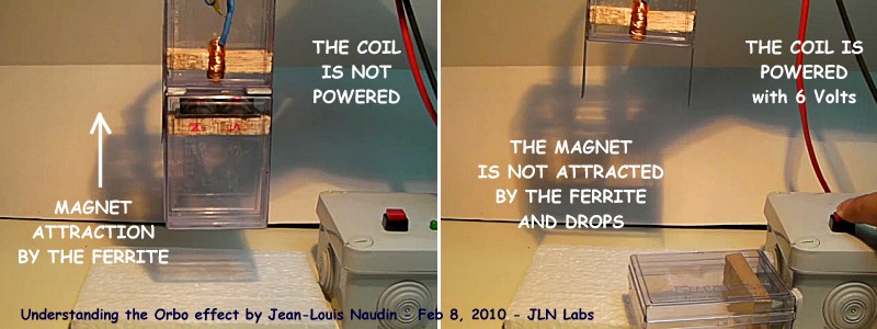
This experiment is
very simple, you need to hold the stator box vertically while the
magnets box hangs magnetically under the stator box. You may
notice that the magnets box is attracted by the ferromagnetic
material of the toroïdal coil due to the magnetic energy. This
is here a FREE ENERGY MAGNETIC FORCE, you don't need to power the
coil to attract the magnets.
Now, if you power the
coil at about 6 Volts DC, the magnetic force attraction vanishes
and the magnets box drops to the ground...
This is an important
key experiment here to understand the Orbo working principle:
Contrary to a common motor, in the case of the Orbo motor, when
you apply current to the stator coil, it is only to release the
magnet AFTER it has produced FREE MECHANICAL WORK !!! Think about
this...
The
second Orbo effect has been demonstrated with this experiment.
3 - Third key
experiment : NO EXTRA
POWER is needed to release the magnet from the TDC position to
the REF position
Here, a bit more
complicated experiment, but this is one of the most important
experiment about the Orbo principle.
A function generator
is connected on the optocoupler input of my Steorn Orbo v4.1
driver. The function generator has been programmed so as to send
the same shape of pulse sent by the motor at full speed. Below
you will find the diagram.
Look at the video of
the test below, you will notice that the alignment of the stator
coil with the middle line of the magnets is very critical at the
"TDC position".
The voltage and the
current have been measured across the coil with a digital
oscilloscope at the REF position (no magnets) and at the TDC
position (with the magnets).
Below you will find
the results.
Below, the current
curve at the REF position (white curve) has been memorised and
superposed to the current curve (yellow curve) at the TDC
position. You may notice that the two current curves are
identical...
The Power (V*I) has
been computed for the two positions ( TDC and REF ) and you may
notice that the power curves are also identical...
You may also notice
the fast rise of the current and then its horizontal shape.
The third Orbo
effect has been demonstrated with this experiment.
A precisely machined device and a very fine alignement of the
toroïdal coils is the key of the success...
To summarize
It is very important
that the toroïdal stator coils must be perfectly aligned with
the middle point between the two magnets :
The magnets
must have the equal strength,
the rotor must
be perfectly balanced and must not have a wobble,
the rotation
axis of the rotor must be frictionless.
These
KEY EXPERIMENTS about the Orbo motor principle presented here
demonstrate fully that :
KEY 1 : The coil inductance
decreases when the magnet goes from the REF position (far
from the stator coil) to the TDC position (close to the
stator coil).
KEY 2 : The mechanical
power is produced only by the attraction of the magnet by
the ferrite of the stator, this is a FREE WORK produced
by the conversion of the magnetic potential energy into
kinetic energy. The
current used to power the stator coil is used only to
release the magnet AFTER it has produced a free
mechanical work.
KEY 3 : The electrical
power (Current * Voltage ) needed to energize the
toroïdal stator coil at the TDC position is EQUAL to the
electrical power for the REF position and this is fully
independant of the position of the magnet of the rotor Vs
the toroïdal stator coil. The electrical input power is
fully decoupled from the output mechanical power.
KEY 4 : When the magnet
leaves the TDC, there is a magnetic energy gain in the
stator coil because the current remains constant during
the increase of the inductance.
Importants
tips for the best tuning :
Use two strong neodymium magnets
oriented N-S towards the toroïdal coil.
The plane of the toroïdal coil must
be perfectly aligned with the middle point of two
magnets.
The gap between the coil and the
magnets must be tuned with a scope so as to find the
point where there is no change in the shape of the
current curve between the TDC and the REF position, this
tuning is very critical.
Use high permeability ferromagnetic
material ( high permeability ferrite core or better
Nanoperm core ).
Don't forget that the free mechanical power
produced by the magnetic attraction of the magnets towards the
ferromagnetic core has no link with the electrical power spent to
release the magnets.
You
will find below, the full video of these KEY EXPERIMENTS
Interesting document to read:
Comments from Jean-Louis Naudin: Why this patent, below, is
interesting for the Orbo motor ?
The patent below is
very interesting because it says that in a common
toroidal coil, each layer is equal to a "one turn
coil" whose axis is parallel to the axis of the
toroid. So, one layer of toroidal coil is equal to a flat
coil of one turn and thus it can tap or produce EMF
outside the torus. So, to counter this interference
effect, the only thing to do is , for each layer of the
toroidal coil, to wound a one turn flat coil along the
circumference of the toroid so as to produce a magnetic
field which nullify the virtual one turn coil created by
each layer of the toroidal coil... This is very simple
and a very important thing to do for canceling the weak
CEMF induced in the toroid by the motion of the magnet
and this is one of the most important key of the Orbo
motor...
SUBSTANTIAL NULLIFICATION OF EXTERNAL MAGNETIC FIELDS
AND LORENTZ FORCES REGARDING TOROIDAL INDUCTORS
Inventor: Lawrence R. Groehl
Assignee: The United States of America as represented by
the Secretary of the Army, Washington, D.C.
Appl. No.: 260,151
Filed: Jun. 13,1994
Main and supplemental windings are combined in a toroidal
inductor to subntially nullify Lorentz Forces on the main
winding and the magnetic field thereof which passes
externally from the inductor.
BACKGROUND OF THE INVENTION
Use of inductors or coils is well know as for storing
electrical energy. As the electromagnetic parameters of
inductors increase however, severe problems are
encountered therewith, for example in power distribution
systems of electric utilities. Because of Lorentz Forces
which result from the interaction of currents with
magnetic fields, structural integrity becomes a primary
consideration. Magnetic fields which radiate externally
from many inductors are also an important consideration
because energy losses result therefrom, and a hazard to
life and equipment.


 Interesting document to read: