Seike's GSEA v3 test created on December 24, 2005 - JLN
Labs - Last update January 7, 2006 Toutes les
informations et schémas sont publiés gratuitement ( freeware )
et sont destinés à un usage personnel et non commercial All informations and
diagrams are published freely (freeware) and are intended for a private use and a non commercial
use.
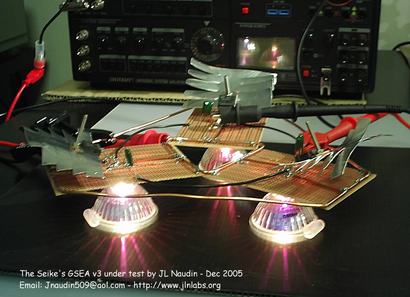
You will find in this
page a new replication of the Seike's G -Strain Energy Absorber
(GSEA) device according to his original description of the
transistorized coil (see below).
The purpose of the
test of the GSEA v3 is to check if the original measurements
conducted by the Professor Seike on his transistorized coil, on
January 1981, can be retreived and replicated easily.
I have not been able
to find the 2SC521A used by Professor Seike, so, I have used
common TIP 3055 NPN transistor.
You may download the full datasheet of the TIP3055 Bipolar Power
Transistor in Pdf, here
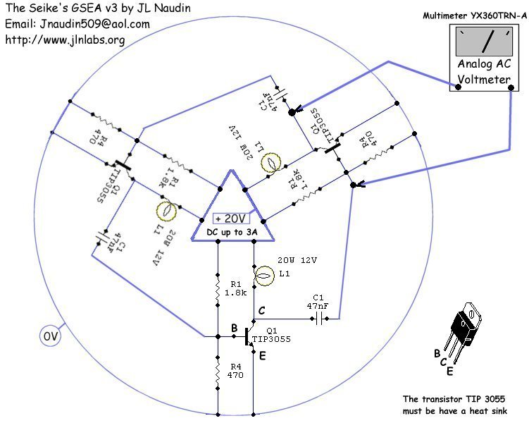
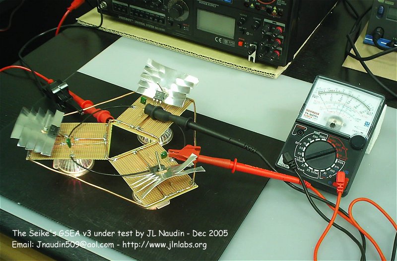
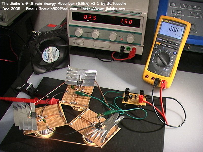
GSEA v3 - TEST SETUP #1
The AC potential across the OUTPUT
must be measured with an Analog voltmeter set to AC mode (scale
0-50 V)
The analog voltmeter used is a SUNWA YX-360 TRN-A (accuracy AC
0-1000V +/- 4%)
GSEA v3.1 - TEST SETUP #2
In this new GSEA setup, for a better
accuracy of the measurement, the output voltage has been
rectified by a bridge of diodes
and filtered by a 1 µF/63V capacitor. The output voltage has
been measured by a digital multimeter (Fluke 189) set in DC.
The Fluke 189 DC Voltage measurement accuracy is 0.03%
The Power supply used is a HQPower PS3020 (0-30V / 0-20A) with DC
Voltage regulation <= 2 x 10e-4 +1 mV
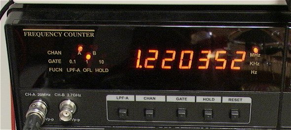
The working frequency of the GSEA v3.1 circuit is about 1.22 Mhz
A cooling fan has been added during the test and a cool-down time
of 15 sec has been respected between each measurement.
A cooling time is required to avoid the impedance change of the
circuit due to the overheating.
As you may notice the best output/input
ratio (1.57) is obtained for 14 Volts DC at the input.
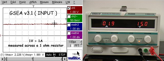
The current INPUT is measured across a 1 ohm resistor in serie
with the GSEA, this can be also checked on the power supply.
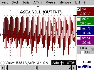
The current OUTPUT is measured across a 1 ohm resistor connected
in serie with ONE LAMP L1 (on 1 branch only).
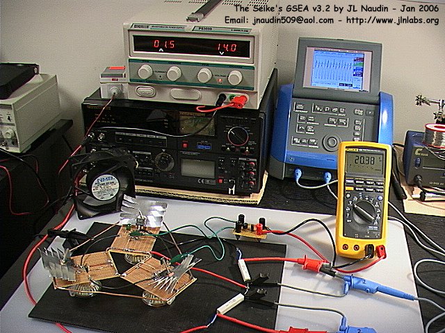
Above, the GSEA v3.2 under tests with a 1 ohm resistor at the
input and a 1 ohm resistor at the output (datas here).
Today, the measured
output voltage on the GSEA v3 seems fully in line with the
original datas of Prof Seike's transistorized coil.
Return to the GSEA home page visitors since December 24, 2005