
MEG Theory
Why it Works, The Simple Explanation
By Dave Squires 11-08-2000
Consider the physical layout of the MEG. You have a stack of neodymium magnets in the center of a rectangular toroidal core. The magnets touch each side of the core on the inside. We have no coils on the core yet.
What does the magnet flux do?
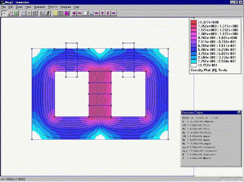
The flux from the magnets will divide equally between each leg of the core. So we have half the flux flowing on the right and half on the left. See picture below of an FEMM simulation of this.
We now place coils on this core. We use two control coils on the top on each side of the magnet stack. And we wind two output coils on each vertical leg on opposite sides. The output coils are not shown on the FEMM simulation pictures.
OK, it is set up. Now we want to switch all the magnet flux to one side by opposing the magnet flux with the opposite control coil. How much flux will the coil need to generate to do this? Well, the answer of course is half the magnet flux since that is what is flowing in that leg. The other control coil is in the off condition, and open circuited, so no current can be induced in it and hence no back-flux generated. The core must not be allowed to reach magnetic saturation or more energy will be required to force the flux to the other side.

Then we turn off the control coil and what happens?
Remember both control coils are now off. The magnet flux will return to its original starting condition of half the flux flowing on each side as in the first picture. Does the magnet need any help to do this? No, of course not. When we did this we also removed half the magnet flux from the other leg when the control coil was on. The first half cycle we only see half the normal induction level in each output coil because at the start we only switch half the magnet flux into one leg and out of the other. So the total change is Bmag/2.
Now on subsequent cycles we let the magnet flux return to its original steady state and let the magnet do the work. Both control coils are off while this happens. Just when the magnet flux reaches its equilibrium point we turn on the other coil and keep the flux change going the other way. Each coil only needs to always switch half the magnet flux not all of it. After the first half cycle we see a 100% change of the magnet flux in each output coil on each cycle for an input power that is half the output. This assumes that we are activating the control coils for half of each cycle. This means we have a theoretical maximum COP of 2.0. We are using the magnet stack as a flux battery and "letting" it do half the work. See the next picture for the second half cycle. These FEMM pictures model the settled state after switching is complete at the zero crossing of the output sinewave.
Now how can we improve it further? Faster switching using more exotic core materials could help. The higher the rate of change of the flux (dB/dt) the more output we get. So higher frequency operation is favored. The Bearden MEG claimed a COP of 5.0. It is very possible that the use of the particular nano-crystalline core material and operating at 40Khz can give a COP of 5.0. Also, changing the duty cycle might help to reduce the input power.
Jean-Louis Naudin has seen a COP of 1.75 using standard grain oriented silicon steel. This tends to confirm my hypothesis above. Core losses might prevent reaching a COP of 2.0 with this material. So at minimum, so far, you can get an OU solid state generator with a gain of 1.75. Just this alone could allow you to reduce your utility bill by about half if you put these devices between your breaker panel and your appliances. You could cascade them also to use 100 watts to get 15KW. It would only take about 9 stages to do this. What Jean-Louis has shown will do the job all by itself with no refinement. You just need bigger magnets, core section, and coils.
Power Gain Factors When Cascading Stages
This table is generated assuming you start with 100 watts input
to stage 1 and size each stage appropriately to handle the power
generated.
Stage Power Gain Power Output
1 1.75 175watts
2 3.06 306watts
3 5.36 536watts
4 9.38 938watts
5 16.41 1,641watts
6 28.72 2,872watts
7 50.27 5,027watts
8 87.96 8,796watts
9 153.94 15,934watts
What this means is you could create a power system to provide all your household power needs with only 100 watts drawn from the power grid. The only real reason to use the power grid is for the right frequency for all your present appliances. Done with an oscillator you could use a battery or hand crank generator to start it up and then run off a capacitor bank for the first stage. If the magnetic transistor idea proves out then one stage or two stages might be sufficient.
![]() Dave Squires ( 11-08-00 )
mailto:djsquires@plix.com
Dave Squires ( 11-08-00 )
mailto:djsquires@plix.com
Return to the MEG project home page