created on February 8, 2003 - JLN Labs - Last update February 8, 2003
All informations in this page are published free and are intended for private/educational purposes and not for commercial applications

created on
February 8, 2003 - JLN Labs -
Last update February 8, 2003
All informations in this page are published free and
are intended for private/educational purposes and not for
commercial applications
|
|||||||||
| Envoyé via Internet | |||||||||
Greetings Jean-Louis:
Finally got around to putting some stuff together to mail. I have
been playing around with lifters since about MAY of 2003 ever
since running across your webpage. Thank you so much for your
commitment to this great source of scientific discovery and
sharing. I hope you will be able to share all the enclosed with
the lifter community.
First:
I would like to share my lifter collection (those I still have),
see attached photo "Lifter Collection"
My first lifter, was a lifter1 that failed to lift - was too
heavy. Next one, a lifter1 also(see photo), I used smaller balsa
wood, finer wire, and less foil. It lifted off okay. Next, I set
about trying to find a better geometric design. I settled on a
Hexagon lifter and its first highly successful flight was 22 June
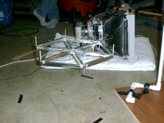
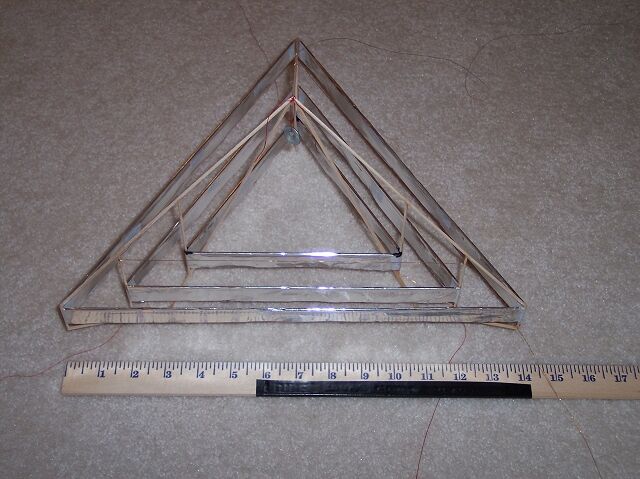
03. (See attached photo "Ferris1.") My next lifter I
built was a much larger one, built around a 6 pointed star design
(see photo). This one did manage to lift off, but not very well.
Think I might be at the power limit of the 17" monitor, not
sure.
Second:
I have been conducting experiments with various element
configurations and trying to put together a power supply. I have
gathered some of the relevant results together in the attached
word document "Element Separation Experiments." Hope
you can find a way to share this information. I think many might
find it useful. I refer back to it often when working on various
designs. I have also attached a word document title "Lessons
Learned." These are some lifter things I have learned that I
wish to share for others to benefit from.
The graph above is the results
of 6 trial runs of 3 different experiments. The objective
was to get a better understanding of how separation of 3
elements affected lift. Constants were element length
(266mm), foil height (33mm), wire distance above foil
(50mm), power from 17” monitor, and nut (6.76grams).
Primary variable was distance between 3 parallel
elements. The first 4 trials were parallel separations,
the 5th was angular separation and the final one was
parallel separation with only the center of 3 elements
with a wire. The first trial returned poor results and
was found to have a bad ground connection to center
element foil (greater then 2 ohms), but was left in to
show how a high ohm ground connection can affect results.
A single element’s lift was measured on the 2nd trial
as a reference. The 2nd through 4th trials were 3 trials
of same setup. The 5th trail I wanted to see how 3
elements touching at one end and increasing separation at
the other end affected lift (increase in angle). The
final trial was inspired by chance. In attempting to
measure only the lift of one element in the second trial,
the center one, I removed the wire from the outer 2
elements in parallel and observed little to no lost of
lift. This prompted the 6th trial. I had to completely
remove the 2 outer elements to get a good reading on lift
of a single element. |
Finally:
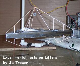
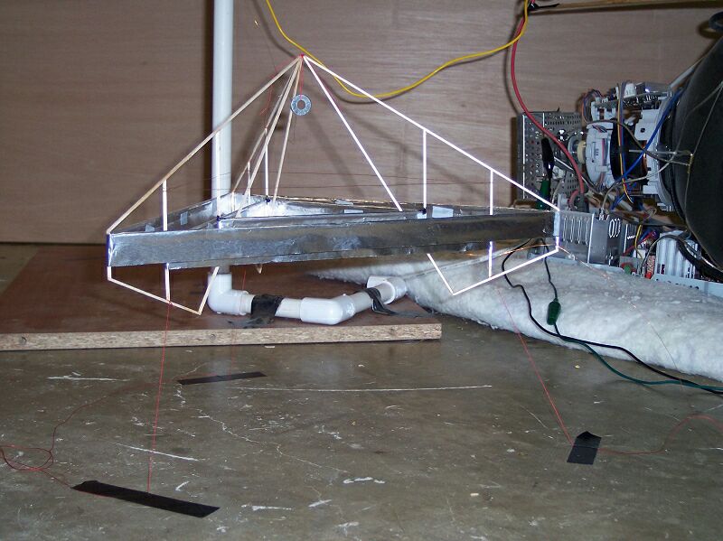
I have attached several photos and a movie of the lifter I built
this past Sunday afternoon (My 7th lifter, I think). I put aside
working on my much bigger and exciting lifter project (which has
much more experimental work and refining of design to go before I
begin construction) to construct this advanced lifter1 design.
This was a design I drew up a while back that never progressed
beyond design till this weekend. It is meant to provide a more
durable triangular craft (I don't favor the single triangular
shape - but it is basic), with a bit more lift over the basic
lifter1, while still being relatively easy to construct in an
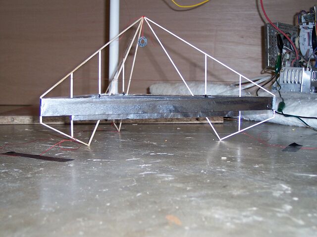
afternoon. This lifter weighed 7.62 grams and is carrying a
washer weighing 1.54 grams, for a total weight of 9.16 grams. You
can see it achieves solid lift with payload. An improvement to
this might be a balsa wood arm to hold the positive wire to the
lifter at a more comfortable distance from the foil. This is an
interesting element configuration that I feel may hold some
design potential. (See my experiment results on element
separation.) It has 3 foils 25mm apart with a single positive
wire over the center foil. The foil is a height of 20mm and the
total element length is about 75cm. The wire is about 35mm above
the foil and the power source is a 17" monitor. You might
notice that I have raised the 2 outer foils about 10mm higher
than the center foil; this helps maintain a 35mm distance from
wire to all 3 foils. ( I need to do some more experiments on this
to determine benefits/disadvantages). For those wishing to
construct one of these I have enclosed a photo of the basic wood
framing (Advanced Lifter Drawing).
| Some Lessons Learned By JL. Trower My first frustration, about a year ago, after running across JL Naudin’s web site was trying to figure out how to get 20-30K volts from a monitor. Ifinally ran across someone’s directions, might have been on Blaze Labs and discovered the positive wire I was searching for was the big wire with suction cup connected to top of monitor’s tube. I learned that you can get a significant shock without even contact. Think I got around 6 inches once to positive wire and got one big zap. I also learned metallic material in the area can build up a charge significantly enough to feel. I read some place that these systems produce ozone, which OSHA has determined is toxic at certain concentrations over time. So it might not be wise to sit in your basement, so fascinated by your first success, that you watch your lifter hover in air for 30 or more minutes. (Not confessing here) My first lifter failed for the same reason many others have, too heavy! I didn’t think 1/16”(2mm) balsa wood was strong enough so I used thinker stuff (maybe 3/32 or 1/8). Foil height was at least 40mm maybe more. And the thin wire I bought was too thick. I suggest using 1/16” (2mm) balsa wood; I have found it at local craft shops and hobby shops. Usually comes in 36” length. Holding the wood near one end, parallel to the ground lets gravity bend the weaker ones further, so you can pick out the stronger pieces. One piece of 1/16” x 36” balsa wood weighs around .4 to .6 grams. So one piece of the next size up (3/32” by 36”) is about .9 to 1.3 grams or 225% heavier!! The 1/16’ stuff seems to work well up to an element length of about 25mm and ok up to about 30mm. If you are using an unsupported post for the wire you may wish to use a larger peace for this, like 1/16” x 1/8”. As for the foil height I now use 30mm wide pieces to get a foil height of 20 mm. (I have not yet experimented with foil height, but seems JL Naudin goes with about 20mm) Thirty six inches of 30mm wide lightweight (cheap) foil weights around 1.3 grams. So if you go with a foil height of 40 or 50mm that weight could double to 2.6 grams. A good easy source of wire I found to be 16-gauge cooper braided speaker wire. A 3-foot piece would work well for a lifter1. Separate the 2 wires then strip off the insulation. I have found warming the wire in a pot of water on the stove helps make this easier and faster. After you have a 3-foot section of bare copper braided wire you can now easily, but carefully, pull out one strand of wire at a time. I mark, with pencil, my posts at heights above the foil 35mm, 40mm, and 45mm. When installing the wire I wrap the starting end about 2 to 3 times around the post at 45mm then snug it up to the next post and wrap it once around at 45mm. Continue till you’re back at the starting post and wrap 2 times or so then leave yourself enough extra to hook up to your positive lead. Wrapping once around each post holds wire were you want it but also allows you to carefully adjust the wire height to optimize your lift. You will find that you can adjust the wire height to increase or decrease the lift of any individual section to help stabilize your lifter and compensate for weight and efficiency differences. I have found reducing my wire to foil height from 50mm to 40mm increases lift by 24% and a 52% increase at 35mm (if I can keep it from arcing at that distance). Still searching for a better way to get a good ground connection to each foil. If you can, check your connections with an ohms meter. I like to try for around 1 ohm or less but never above 2 ohms. So using a 17” monitor, one piece of 1/16” x 36” balsa wood, 36” x 30mm strip of aluminum foil, 6 feet of copper wire, super glue (Cyanoacrylate), Scotch tape, and some thread, and getting your wire distance down to about 35mm you should get about a lifter1 with about 10” (25mm) sides that weighs between 2.5 and 3 grams. (If you use the next size wood and 40mm foil it may weigh up around 5 grams) You should be able to get around .0454 grams of lift per cm of element, so at 25cm sides: (25cm)(3 sides)(.0454grams/cm) = 3.4 grams of lift. Not much extra lift to add any extra anything with only three, 25 mm sides (elements). When you restrict the lifter’s flight height with thread manually test it in all directions to be sure that the positive wire cannot possibly come near the negative foil (at least 80-100mm at the closest) before applying any power to it. For those that do not have access to a scale to weigh grams try this. Get a yardstick, a cheap wood one will work well. Find something that has a thin top edge to balance it on (I use a 3 side drafting ruler) and a few U.S. pennies (after 1982). Find the balance point of the yardstick, this compensates for any variants in the yardstick. Place the object to weigh near one end (the greater the distance the more accurate your results) of the yardstick then place a few pennies on the other side. Carefully slide your pennies along the yardstick till it is balanced. Record the 2 lengths, pennies to balance point and object to balance point. Now you’re ready to calculate your objects weight. Example: weight of 5 pieces of 1/16 x 36” balsa wood (9.625 inches object distance)(5 balsa wood) = (6 inches pennies distance)(2 pennies)(2.532 grams weight of a U.S. penny) Balsa wood = (6)(2)(2.532) / (9.625)(5) = .6314 grams Note: Use center of object as place to take measurement from, assuming that is center of gravity for the object. (I stepped on my yardstick so it is now a 2-foot ruler) |
Hope some find this stuff helpful and
inspiring. Thanks to all those with the innovative designs (I
enjoy studying each one) and to Jean-Louis for making this all
possible.
JL Trower
Michigan, USA
Notes from Jean-Louis Naudin : Congratulations
to JL Trower for his very good test report and thank you very
much to him for the sharing of his experimental tests results for
the benefit of all.
Return to the Lifters Builders page