G STRAIN ENERGY ABSORBER -
GSEA 1.1 - TEST REPORT
V 1.1 - February 97 - Jean-Louis Naudin
MAIN TESTS RESULTS
After you have check these all point above, you could start your G Strain absorber circuit and see the NEGATIVE POWER FLOWING in the circuit.......
The Voltage has been mesured on a 12 v DC battery and Current has been mesured through a 1 ohm with a scope probe.
Oscilloscope : PM3215 2x50 Mhz Philips with 1/10 corrected probes.
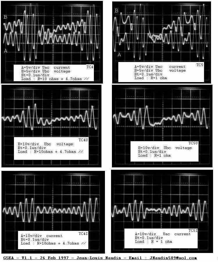
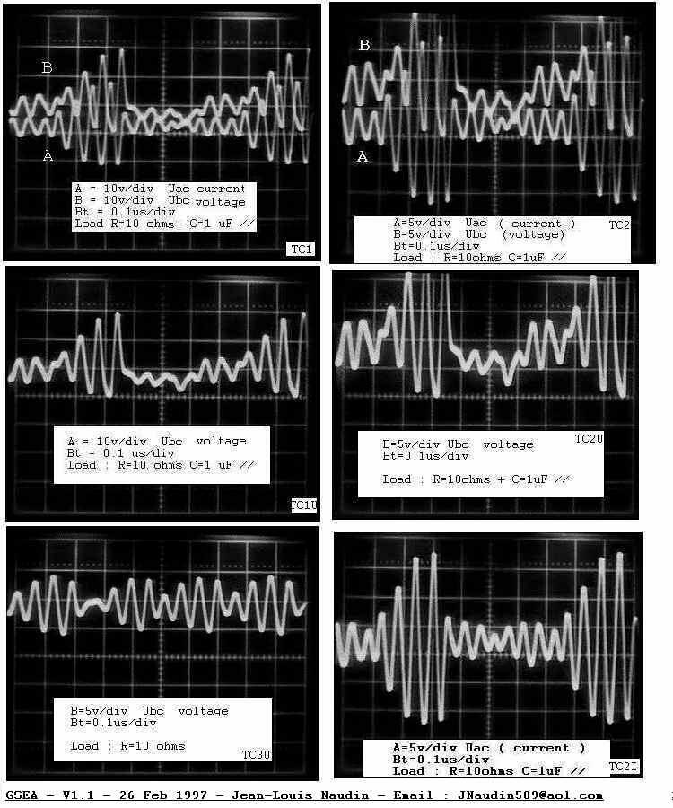
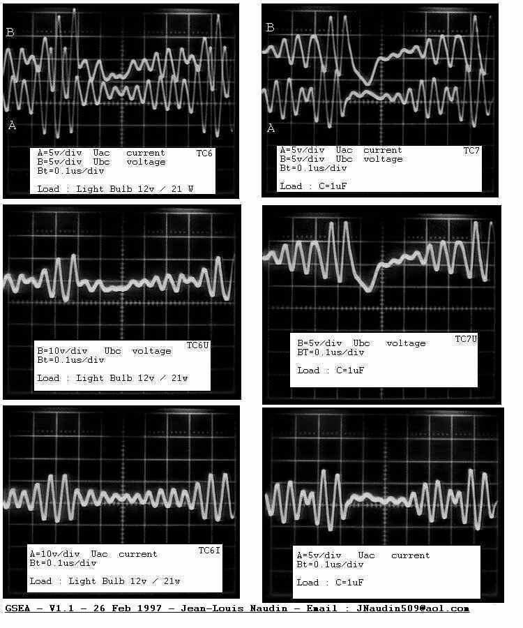
The correct phase of polarity has been checked during the test ( channel A non inverted , channel B inverted mode ). The scope signal represent the real aspect of current/voltage. You could observe the reverse current and voltage, the circuit act as a generator VS battery during some period. The value of capacitors C1, C2, C3 have no significant influence on frequency and on reverse power. Notice that you have no inductive component in that circuit. I have tested successfuly this circuit with BU407, 2N6292 transistors.
GSEAtest1 - points Ux,Uy,Uz /ground and Uxz, Uyz phases
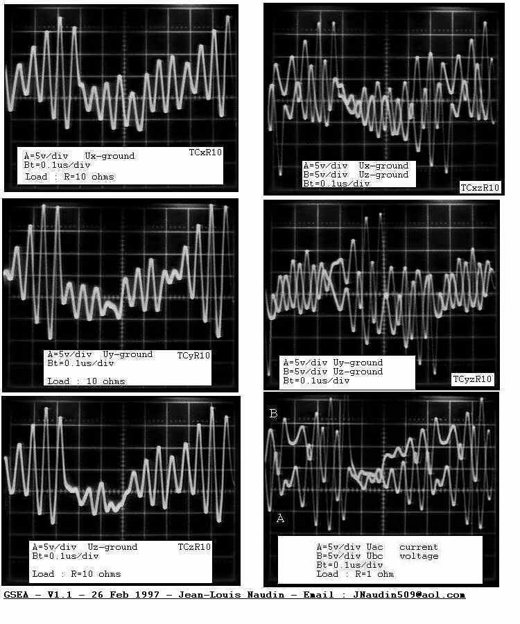
GSEAtest2 - Load : R=10ohms + 4.7ohms in // and Load : R=1ohm
GSEAtest3 - R=10ohms with C=1uF in // - (voltage/current)
GSEAtest4 - Load : Light bulb 12v/21w - (voltage/current)
Return to GSEA main page