Electromechanical
controlled Lifter
by
John Rigg
created on
March 11, 2003 - JLN Labs -
Last update March 11, 2003
All informations in this page are published free and
are intended for private/educational purposes and not for
commercial applications
|
|||||||||
| Envoyé via Internet | |||||||||
Hi, John Rigg here in Elk WA. USA
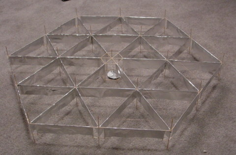
On my 4th Lifter I decided to try a electro mechanical control idea to see if a balance system could be built , so as to remove the 3 tether lines.
I failed in this respect but was able to control the balance
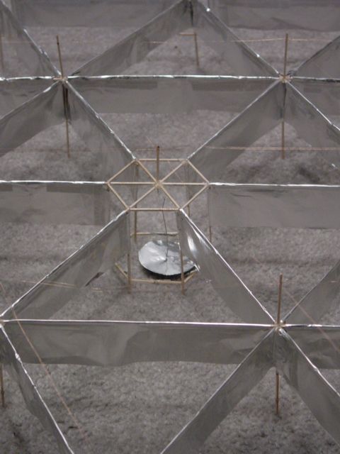
of the lifter. I isolated the 12 outside lifter cells foil
sections and brought them to a center commutator area. I then
humg a foil disc that was grounded. The idea was that if the
lifter tipped to the left for example the foil disc pendulum
would move closer to the foil commutator and supply more ground
to the lifter cells on the side that was lowest. This did and
does work you can control the outside cells and use then as
balance thrusters, the problem is with the simplistic foil disc
pendulum. It has no damping so it will swing all over the place
once placed in motion, so the lifter looked allot like a childs
top just before it falls over. But again I was able to control
the thruster cells and that was the
main goal.
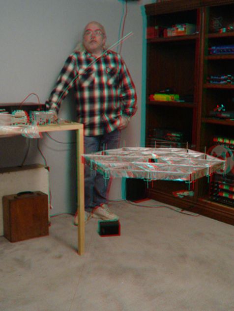
I have attached pictures of the lifter commutator area and a ANAGLYPH picture (3d, red/blue glasses required) of the ship lifted with the balance control parts removed and out side cells grounded. NASA uses 3d anaglyphs as I'm sure you know as it is a good way to show depth, the Mars explorer is a good example, and moon rock pictures that can be found on the web. There is a link for free glasses on my site or you can get them at most any comic book shop.
John
You can see other lifter pictures at my web site.
http://www.robothut.robotnut.com
See also the :
 Lifters builders
and tests feed-back
Lifters builders
and tests feed-back ![]()
Return to the Lifters Builders page